Behavior Analysis
- Public Configurations
- Context
- Setting Global Parameters (Configuring Frontend Behavior Analysis on the LDU)
- Setting Global Parameters (Configuring Backend Behavior Analysis on the LDU)
- Setting Global Parameters (Configuring Backend Behavior Analysis on the iClient S100)
- Setting Global Parameters (Configuring Frontend Behavior Analysis on the iClient S100)
- Intrusion Detection
- Loitering Detection
- Abandoned Object Detection
- Removed Object Detection
- Tripwire Crossing Detection
- Area Entry Detection
- Area Exit Detection
- Fast Movement Detection
- Electric Bike Detection
- Parking Detection
Public Configurations
Context
Principles
This intelligent service can be implemented:
- On cameras
Cameras perform intelligent analysis using its own algorithm, and report alarms and snapshots to the HWT-IVS1800. The HWT-IVS1800 stores and manages alarms and displays alarms on the client. Figure 4-114 shows the process.
- On the HWT-IVS1800
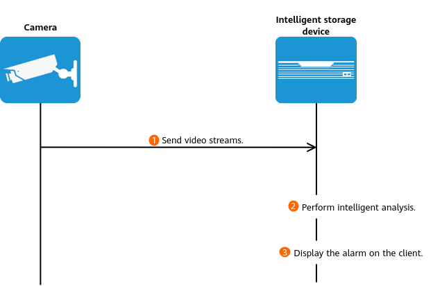
Cameras directly send video to the HWT-IVS1800. The HWT-IVS1800 performs intelligent analysis based on its own algorithms, stores and manages alarms, and displays alarms on the client. Figure 4-115 shows the process.

Configuration Process
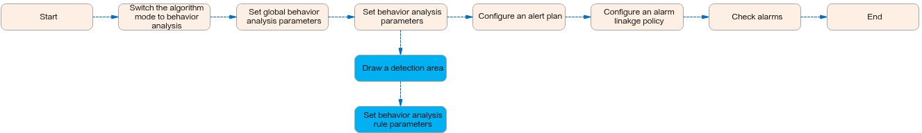
- The behavior analysis function implemented on intelligent cameras can be configured on the LDU or in the camera web system.
Figure 4-116 shows the configuration process on the LDU. For details about the configuration in the camera web system, see the product documentation of the corresponding camera.
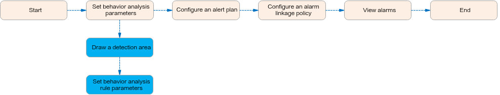
- Behavior analysis using the HWT-IVS1800 intelligence can be configured only on the LDU. Figure 4-117 shows the process of configuring behavior analysis on the LDU.
Differences
Table 4-96 describes the differences between the intelligent analysis using cameras and that using the HWT-IVS1800.
Intelligence Type |
Camera intelligence |
HWT-IVS1800 intelligence |
|---|---|---|
Requirement on the Camera |
|
|
Others |
|
|
Application Limitations
- For details about the data retention period and clearance rules, see Data Clearance Rules.
- Behavior analysis is not supported for video encoded in the MJPEG format.
- To configure intelligent analysis for cameras on the iClient S100, the camera version must be 9.0.0 or later.
Related Feature Operations
For details about operations related to behavior analysis, see the feature guide.
Setting Global Parameters (Configuring Frontend Behavior Analysis on the LDU)
Context
- When Send full image as metadata is enabled:
- The intelligent attribute of the camera is automatically set to Others.
- The media stream function has been enabled in the camera web system. For details, see the camera product documentation.
- Cameras have been configured to synchronize time with the HWT-IVS1800. This function is enabled by default. For details, see Configuring Time Synchronization from a Camera to the HWT-IVS1800.
Procedure
- Log in to the LDU as the admin user. (
 Logging In to the LDU)
 - Disable common intelligent analysis, target recognition, and situation analysis of the camera.
- For details about how to disable common intelligent analysis, see Feature Guide > Intelligence > Common Intelligence in the IVS1800 Product Documentation.
- For details about how to disable target recognition, see Enabling Target Recognition.
- For details about how to disable situation analysis, see Feature Guide > Intelligence > Situation Analysis in the IVS1800 Product Documentation.
- Set the camera algorithm mode. You need to set the camera algorithm mode only for some camera models. If the camera algorithm mode is not displayed, skip this step.
- Click
 in the upper left corner.
 - Choose Intelligent Application > Camera Intelligence > Algorithm Mode.
- Set the camera algorithm mode, as shown in Figure 4-118.
Table 4-97 Parameter description
Parameter
Setting
Algorithm Mode
Select Behavior Analysis.
- Click
- Set global behavior analysis parameters.To view the configuration guide video, you can click
 on the Configuration tab page, and scan the QR code.
- Choose Intelligent Applications > Camera Intelligence > Behavior Analysis > Global Configuration.
- Set global parameters, as shown in Figure 4-119.
Table 4-98 describes the key parameters and buttons.
Table 4-98 Parameter/Button descriptionParameter/Button
Description

Button for enabling or disabling global behavior analysis configuration.
Min Target
Minimum resolution of an object that can be detected on video images in the CIF (352 x 288) resolution.
No alarm is generated when the resolution of a detected object is less than the value of this parameter.
Max Target
Maximum resolution of an object that can be detected on video images in the CIF (352 x 288) resolution.
No alarm is generated when the resolution of a detected object is greater than the value of this parameter.
Target Detection Sensitivity
Sensitivity for triggering target detection alarms.
The options include lower, low, standard, high, and higher.
Higher sensitivity indicates a higher possibility of triggering alarms, which may lead to false alarms. For example, after you set high sensitivity for intrusion detection, a false alarm may be reported when a target passes by a sensitive area.
Lower sensitivity indicates a lower possibility of triggering alarms, which may lead to missing alarms. For example, after you set low sensitivity for tripwire crossing detection, an alarm may not be reported when a target passes one end of a tripwire.
Max Objects
Maximum number of objects for intelligent analysis. Set this parameter as prompted.
Send only the first alarm of a single target
Indicates whether to allow the camera to send the alarm only once for the same alarm event.
Send Metadata
The function is enabled by default.
Indicates whether to send metadata updates. After this function is enabled, the camera will send metadata updates such as intelligent analysis rules and intelligent analysis results as well as live video to the upper-level video and image management platform. If the platform requests metadata streams, enable this function.
Metadata sending panorama
The function is enabled by default.
Indicates whether to allow the camera to send the full image, object frame, and rule frame generated upon alarm occurrence as matadata to the upper-level video and image management platform. Then the platform can superimpose the object frame and rule frame on the full image.
You are advised to enable this function in behavior analysis scenarios.
Alarm sending panorama
Indicates whether to allow the camera to send the full image as general metadata when an alarm is generated to the video security platform.
Superimpose target frames on full images
Indicates whether to allow the camera to send the full image, object frame, and rule frame generated upon alarm occurrence as matadata to the upper-level video and image management platform.
You are advised to disable this function in behavior analysis scenarios.
Shadow Removal Mode
Mode in which the shadow is removed. The shadow generated when objects are moving affects the detection size. Set the parameter based on the site requirements.
NOTE:- In a scenario with no shadow or small shadows, Weak shadow is recommended to ensure complete detection of objects.
- In a scenario with obvious large shadows, Strong shadow is recommended to cut objects from shadows to make bounding rectangles closer to the object sizes or cut objects overlapped with shadows to separately display the objects.
Background Update Frequency
Speed of integrating an object into the background. A larger value indicates quicker object integration.


Setting Global Parameters (Configuring Backend Behavior Analysis on the LDU)

This feature applies only to PoC scenarios outside the Chinese mainland.
Setting Global Parameters (Configuring Backend Behavior Analysis on the iClient S100)
Prerequisites
You have installed the behavior analysis algorithm plug-in on the HWT-IVS1800.
Scenario Description
- After local intelligence is enabled or an analysis task is created for a camera, do not modify the attributes of the camera. Otherwise, target recognition and video structuring tasks will become invalid, and you will need to delete and recreate the tasks.
- Cameras have been configured to synchronize time with the HWT-IVS1800. This function is enabled by default. For details, see Configuring Time Synchronization from a Camera to the HWT-IVS1800.
Global Configuration
When creating a behavior analysis task, you can set advanced rule parameters (global parameters) based on the site requirements. The parameter settings take effect for all analysis rules of the current analysis tasks.
- On the iClient S100 home page, choose .
- Right-click an HWT-IVS1800 and choose Task Management.
- Click New Task. In the New Task dialog box that is displayed, choose Global Configuration in the navigation tree on the left, select a camera on the right, and set the algorithm, video type, and schedule parameters as required, as shown in Figure 4-120.
Table 4-99 Parameter description
Parameter
Description
Camera
Select the camera for which you want to create an analysis task.
Algorithm
Select an algorithm as required.
- Behavior analysis
- Target recognition
- Video structuring
Video Type
Select a video type as required.
- Live
- Recording
Set Schedule
Set the time segment for executing the analysis task as required.
Max Objects
Maximum number of objects that can be analyzed and processed in a detection area.
Recognition Sensitivity
Sensitivity for detecting objects in a detection area for the analysis task. Higher sensitivity indicates a higher probability of triggering alarms and a higher false positive rate.
- high
- medium
- low
- lower
- lowest
- Click Save.
Select a behavior analysis rule and configure the rule. For details, see the following sections.

Setting Global Parameters (Configuring Frontend Behavior Analysis on the iClient S100)
Prerequisites
- The intelligent attribute of the camera is automatically set to Others if Send full image as metadata is enabled.
- Cameras have been configured to synchronize time with the HWT-IVS1800. This function is enabled by default. For details, see Configuring Time Synchronization from a Camera to the HWT-IVS1800.
- You have enabled the alarming function so that required alarms can be reported to the iClient S100. To enable alarming, perform the following steps:
- On the iClient S100 home page, choose .
- Double-click a camera connected to the HWT-IVS1800, click the System Parameters tab, and set Alarming to Enable.
- Click Save.
Procedure
- On the iClient S100 home page, choose Maintenance Management > Smart Configuration.
- Select a camera for which you want to configure a behavior analysis policy.
- Choose . On the tab page shown in Figure 4-121 that is displayed, set global parameters.
- Toggle on Enable Behavior Analysis and set global parameters. Table 4-100 describes the parameters.
Table 4-100 Parameter description
Parameter
Description
Send Metadata
Indicates whether to send metadata when the HWT-IVS1800 is connected to the upper-level platform.
If this function is enabled, cameras will send metadata such as snapshots and structured data to the upper-level platform. Then the upper-level platform can perform search by criteria based on the metadata sent by the lower-level HWT-IVS1800.
Enhanced perimeter detection
Indicates whether to allow the camera to send the full image generated upon alarm occurrence to the upper-level video and image management platform as metadata.
Alarm suppression
Indicates whether to allow the camera to send the alarm only once for the same alarm event.
Superimpose intelligent information on alarm-triggered snapshots
Indicates whether to superimpose the target frame and rule frame that trigger alarms on full images sent as metadata.
Shadow Mode
Shadow strength.
The options include Weak, Common, and Strong.
Detection sensitivity
Sensitivity for triggering target detection alarms.
The options include Lower, Low, Standard, High, and Higher.
Higher sensitivity indicates a higher possibility of triggering alarms, which may lead to false alarms. For example, after you set high sensitivity for intrusion detection, a false alarm may be reported when a target passes by a sensitive area.
Lower sensitivity indicates a lower possibility of triggering alarms, which may lead to missing alarms. For example, after you set low sensitivity for tripwire crossing detection, an alarm may not be reported when a target passes one end of a tripwire.
Background update rate
Speed of integrating an object into the background. A larger value indicates quicker object integration.
Min. object size
Minimum size of an object that can be detected on video images in the CIF (352 x 288) resolution.
No alarm is generated when the size of an object is less than the value of this parameter.
NOTE:The minimum object size supported by behavior analysis is 5 x 5 pixels (at the video resolution of 352 x 288 pixels).
Max. object size
Maximum size of an object that can be detected on video images in the CIF (352 x 288) resolution.
No alarm is generated when the size of an object is greater than the value of this parameter.
NOTE:The maximum object size supported by behavior analysis is 200 x 200 pixels (at the video resolution of 352 x 288 pixels).
- Toggle on Enable Behavior Analysis and set global parameters. Table 4-100 describes the parameters.
- Click Save.

Intrusion Detection
Feature Description
Definition
The system automatically generates an alarm when an intrusion is detected.
- Allows users to specify multiple polygonal detection areas.
- Detects and distinguishes multiple objects that enter a specified area, and generates alarms.
- Displays alarm information including the alarm type, occurrence time, duration, and object labeling.
Customer Benefits
The system automatically detects key information in video feeds through intelligent analysis, reducing labor costs and improving detection efficiency. Different intelligent analysis functions apply to different scenarios.
Application Scenario
If no one is allowed to enter or approach an area, the intrusion detection function can be used to keep the area under detection.
Requirements
NE |
Version Requirement |
License Requirement |
Function |
|---|---|---|---|
HWT-IVS1800-D/HWT-IVS1800-E |
11.1.0 and later versions |
N/A |
Handles intrusion alarms. |
iClient S100 |
V1.6.0 and later versions |
N/A |
Allows users to configure behavior analysis and alarm display in the camera web system. |
SDC |
Common perimeter detection: 8.0.0 and later versions (configurable on the LDU only in 8.2.0 and later versions) Enhanced perimeter detection: 9.0.0 and later versions |
N/A |
Supports behavior analysis (perimeter detection). |
Application Limitations
- Onsite conditions such as illumination and shooting angles affect the detection accuracy.
- This feature is supported only by cameras connected through HWSDK.
- Alarms can be triggered concurrently for a maximum of nine objects.
Feature Configuration (Based on Cameras)
Scenario Description
Table 4-101 describes the support for this feature in different client scenarios.
Client |
Feature Support |
Reference |
|---|---|---|
LDU |
Supported |
For details, see Procedure (on the LDU). |
Camera web system |
Supported |
Complete the configuration by referring to the product documentation of cameras. |
iClient S100 |
Supported |
For details, see Procedure (on the iClient S100). |
Prerequisites
- You have connected a camera that supports intelligent analysis.
- You have set the parameters listed in Setting Global Parameters (Configuring Frontend Behavior Analysis on the LDU) on the LDU.
- You have enabled behavior analysis for the camera and set global parameters on the iClient S100. For details, see Setting Global Parameters (Configuring Frontend Behavior Analysis on the iClient S100).
- Alarm linkage has been configured on the iClient S100. For details, see Configuring Alarm Linkage.
Procedure (on the LDU)
To view the configuration guide video, you can click  in the upper left corner on the Configuration tab page, and scan the QR code.
- Log in to the LDU as the admin user. ( Logging In to the LDU)
- Click
 in the upper left corner.
 - Choose .
- Configure intrusion detection, as shown in Figure 4-122.
Table 4-102 describes the key parameters and buttons.
Table 4-102 Parameter/Button descriptionType
Parameter/Button
Description
Detection Area
Detection Object
Type of objects that can be detected.
- Pedestrian
- Motor vehicle
- Non-motorized vehicle
No.
ID of a detection area. A maximum of four detection areas can be drawn.
Operation
Column containing the icons for drawing or deleting a detection area on the live video image.
Switch
Button for enabling or disabling a detection area.
Sound And Light Alarm
NOTE:The configurations of this function cannot be applied to other devices.
Audio switch/Twinkle switch
Indicates whether to produce audible alarms (playing audio files) or visual alarms (blinking light) when an alarm is triggered.
Audio Output
Audio file to be played when an alarm is triggered.
- You can directly use this function when an intelligent IR/white-light camera with intercom is used.
- To use this function when a camera other than the intelligent IR/white-light camera with intercom is used, you need to set audio parameters for the camera and connect the camera to an external audio output device.
Frequency
Number of times for playing an audio file when an alarm is triggered.
Twinkle Freq
Frequency at which the light blinks when an alarm is triggered. You can set this parameter to Low frequency, Medium frequency, or High frequency as required.
Currently, the visual alarm (blinking light) function is available only for intelligent IR/white-light cameras with intercom. You need to set light-related parameters.
Twinkle Time(s)
Period in which the light blinks when an alarm is triggered.
Alarm Settings
Alarm Sensitivity
Detection sensitivity of the system.
The value ranges from 1 to 100. A larger value indicates higher sensitivity.
Alarm Interval (s)
Interval at which alarms are checked, in seconds.
Pre-determined Alarm Position
Part of an object based on which detection is performed.
- Center: An object can be detected only when its central part enters the detection area.
- Top: An object can be detected only when its top part enters the detection area.
- Bottom: An object can be detected only when its bottom part enters the detection area.
The criteria for determining whether an object enters the detection area are related to Pre-determined Alarm Position. For example, if Pre-determined Alarm Position is set to Center, an alarm is triggered when the central part of an object enters the detection area.
- Configure an alert plan, as shown in Figure 4-123.
Table 4-103 describes the key parameters and buttons.
Table 4-103 Parameter/Button descriptionParameter/Button
Description
Add
Button for adding an alert plan. A maximum of eight alert plans are supported.
Delete All
Button for deleting all alert plans.

Button for enabling or disabling an alert plan. If you toggle on Status, the alert plan takes effect.
Day
Date on which an alert plan is executed.
The default value is Every Day.
Mode
Mode in which an alert plan is executed.
- Weekly
- One-off
- Configure an alarm linkage policy, as shown in Figure 4-124.
Table 4-104 describes the key parameters.
Table 4-104 Parameter descriptionType
Parameter
Description
Common Linkage
Display ID
Indicates whether to display the status icon of the camera that triggers an alarm on the live video viewing page. This function is used to notify users of an alarm generated by the current camera.
Full-Screen Alarm
Indicates whether to display alarms in full screen mode.
After this function is enabled, if a camera triggers an alarm and the live video viewing page is displayed on the LDU, the live video of the camera is played in full screen mode for 5s.
CAUTION:If another alarm is generated when live video is being played in full screen mode, this function is not triggered.
Send Email
- Indicates whether to send email notifications. After this function is enabled, the system sends an email to the configured email recipient when a service alarm is generated.
- You can click
 to customize the alarm email recipient and email body.
The email address for sending service alarms needs to be customized on the OMU portal.
For details about how to set the email address for sending service alarms, see How Do I Configure Connection to the SMTP Server?.
Recording
Channel
Camera to be linked to record video when an alarm is triggered.
Duration(s)
Customized recording duration. The value ranges from 5 to 3600, in seconds. You are advised to set this parameter to a value greater than or equal to 60 (default).
Triggered Snapshot
Channel
Camera to be linked to take snapshots when an alarm is triggered.
NOTE:If both snapshot taking and email sending are configured for alarm linkage, you can obtain both the alarm-triggered snapshots and the snapshots sent in the email.
Stop Recording
Channel
Camera to be linked to stop video recording when an alarm is triggered.
I/O Alarm
Channel ID
Alarm reporting channel.
Duration(s)
Customized alarm linkage duration.
The value ranges from 1 to 3600, in seconds.
NOTE:If the specified alarm linkage duration is different from the I/O alarm output duration configured in How Do I Connect Cables and Configure Alarm Input and Output Ports?, the shorter alarm duration is used.
For example, if the I/O alarm output duration is set to 20s and the alarm linkage duration is set to 30s, the actual alarm output duration is 20s.
Invoke Preset Position
Channel
Camera to be linked. When a service alarm is generated, the linked camera rotates to the specified preset position.
Before enabling preset position linkage, ensure that a preset position has been configured for the camera to be linked. For details about how to configure a preset position, see Feature Configuration.
Device
Name of the camera that is linked to a preset position.
Position
Preset position linked to the camera.


Procedure (on the iClient S100)
- On the iClient S100 home page, choose Maintenance Management > Smart Configuration.
- Select a camera for which you want to configure a behavior analysis policy.
- Choose and set related parameters.
- Set parameters in the Parameter Settings area. Table 4-105 describes the parameters.
Table 4-105 Parameter description
Parameter
Description
Detection Target
Type of objects that can be detected. (This parameter is not involved when the behavior analysis type is abandoned object detection, removed object detection, or electric bike detection.)
- Pedestrian
- Motor vehicle
- Non-motorized vehicle
Alarm Detection Interval(s)
Interval at which the system checks for new alarms, in seconds. If any alarm is detected, the system reports the alarm to the iClient S100.
NOTE:To prevent a flood of alarms, the system reports only one alarm even if it detects multiple alarms within the specified interval.
Target Recognition Mode
Part of an object based on which detection is performed.
- centered: An object can be detected only when its central part enters the detection area.
- Bottom: An object can be detected only when its bottom part enters the detection area.
- tops: An object can be detected only when its top part enters the detection area.
Sensitivity
Detection sensitivity.
The value ranges from 1 to 100. A larger value indicates higher sensitivity.
- Set audible and visual alarm parameters. Table 4-106 describes the parameters.
Table 4-106 Audible and visual alarm parameters
Parameter
Description
Requirement on the Camera
Enable audio alarms
Indicates whether to produce audible alarms (play audio files) when an alarm is triggered.
- You can directly use this function when an intelligent IR/white-light camera with intercom is used.
- To use this function when a camera other than the intelligent IR/white-light camera with intercom is used, you need to set audio parameters for the camera and connect the camera to an external audio output device.
Audio file
Audio file to be played when an alarm is triggered.
To import an audio file to the iClient S100, choose Maintenance Management > Video Device > Device List on the home page, double-click the required camera that is connected to a device, and add an audio file on the Audio Channel tab page.
Playback times
Number of times for playing an audio file when an alarm is triggered.
Enable light flashing alarm
Indicates whether to produce visual alarms (blinking lights) when an alarm is triggered.
Currently, these functions are available when an intelligent IR/white-light camera with intercom is used. You need to set light-related parameters.
White light illuminator
Frequency at which the light blinks when an alarm is triggered. You can set this parameter to Low, Middle, High, or Steady on as required.
Flash duration (s)
Period in which the light blinks when an alarm is triggered.
- Set area parameters, as shown in Figure 4-125. Table 4-107 describes the parameters and buttons.
Table 4-107 Area settings
Parameter/Button
Description
Area
Button for adding a detection area. A maximum of four detection areas can be configured for analyzing a type of behavior. A maximum of 10 detection areas can be configured for analyzing all types of behavior.
You can select and drag the detection area or change its shape and size.
Delete
Button for deleting a selected detection area.
Status
- If the parameter is toggled on, the frame of a detection area turns red and the detection takes effect.
- If the parameter is toggled off, the frame of a detection area turns white and the detection stops.
- Set plan parameters. Table 4-108 describes the parameters.
When the iClient S100 and an HWT-IVS1800 are in different time zones, the time set in the Plan Settings area refers to the time of the HWT-IVS1800.
Table 4-108 Plan settingsParameter/Button
Description
Add
Button for adding an alert plan. A maximum of eight alert plans are supported.
All Delete
Button for deleting all alert plans.
Start Time/End Time
Time segment during which alert is to be deployed.
Date
Date on which an alert plan is to be executed.
- Every day
- Monday to Sunday
Mode
Indicates whether to cyclically execute an alert plan.
- Weekly
- One-off
Operation
To delete the current alert plan, click
 in the Operation column.
- Set parameters in the Parameter Settings area. Table 4-105 describes the parameters.
- Click Save.

Feature Configuration (Based on the HWT-IVS1800)
This feature applies only to PoC scenarios outside the Chinese mainland.
Scenario Description
- Table 4-109 describes the support for this feature in different client scenarios.
Client |
Feature Support |
Reference |
|---|---|---|
LDU |
Supported |
For details, see Procedure (on the LDU). |
iClient S100 |
Supported |
For details, see Procedure (on the iClient S100). |
- After local intelligence is enabled or an analysis task is created for a camera, do not modify the attributes of the camera. Otherwise, target recognition and video structuring tasks will become invalid, and you will need to delete and recreate the tasks.
Prerequisites
You have set the parameters listed in Public Configurations.
Procedure (on the LDU)
To view the configuration guide video, you can click in the upper left corner on the Configuration tab page, and scan the QR code.
- Log in to the LDU as the admin user. (
 Logging In to the LDU)
 - Right-click on the desktop and choose Intelligent Application.
- Choose Local Device Intelligence > Behavior Analysis > Intrusion.
- Set basic intrusion detection parameters, as shown in Figure 4-126.
Table 4-110 describes the parameters.
Table 4-110 Parameter descriptionParameter
Description

Button for enabling or disabling intrusion detection.
Detection Object
Type of objects to be detected. The options include Pedestrian and Motor vehicle. After you select a detection object type, the camera automatically reports an intrusion alarm upon detecting an object of the selected type.
No.
ID of a detection area. A maximum of four detection areas can be drawn.
Operation
Column containing the icons for drawing or deleting a detection area on the live video image.
You can draw detection areas based on the following rules:
- You are advised to draw lines clockwise. The lines you draw cannot cross each other or form a sharp acute angle. Otherwise, detection areas may fail to be drawn.
- Do not draw polygonal areas that overlap with each other. Otherwise, false negatives may occur.
Min Target
Minimum resolution of an object that can be detected, in pixels.
Max Target
Maximum resolution of a target that can be detected, in pixels.
Pre-determined Alarm Position
- Center: An object can be detected only when its central part enters the detection area.
- Top: An object can be detected only when its top part enters the detection area.
- Bottom: An object can be detected only when its bottom part enters the detection area.
Target Detection
Sensitivity for the system to trigger alarms when detecting objects in the detection area.
Higher sensitivity indicates a higher probability of triggering alarms and a higher false positive rate. The options are as follows:
- Lowest
- Low
- Lower
- Medium
- High (default)
Max Targets
Maximum number of objects that can be analyzed and processed in a detection area.
Alarm Interval(s)
Interval at which the system checks for new alarms.
To prevent a flood of alarms, the system reports only one alarm even if it detects multiple alarms within the specified interval.
- Configure an alert plan, as shown in Figure 4-127.
Table 4-111 describes the key parameters.
Table 4-111 Parameter descriptionParameter
Description
Add
Button for adding an alert plan.
Delete All
Button for deleting all alert plans.
Status
Indicates whether to enable an alert plan.
Start Time/End Time
Execution duration of the alert plan.
Date
Date on which an alert plan is to be executed.
- Every day
- Monday to Sunday
Mode
Indicates whether to cyclically execute an alert plan.
- Weekly
- One-off
Operation
Column containing the icon for deleting the alert plan.
- (Optional) Configure the intrusion detection alarm linkage, as shown in Figure 4-128.
Table 4-112 describes the parameters.
Table 4-112 Parameter descriptionParameter
Description
Severity
Alarm severity. The default value is Minor. You do not need to set this parameter.
Channel
Camera to be linked to record video when an alarm is triggered.
When a camera triggers an alarm, the selected camera starts to record video.
Snapshot channel
Camera to be linked to take snapshots when an alarm is triggered.
When a camera triggers an alarm, the selected camera starts to take snapshots.
NOTE:If both snapshot taking and email sending are configured for alarm linkage, you can obtain both the alarm-triggered snapshot and the snapshot sent in the email.


Procedure (on the iClient S100)
- On the iClient S100 home page, choose .
- Right-click a certain HWT-IVS1800 and choose Task Management.
- Click New Task. In the New Task dialog box that is displayed, choose the desired behavior analysis task in the navigation tree on the left, and set related parameters, as shown in Figure 4-129.
Table 4-113 General parameters
Parameter
Description

Indicates whether to enable the current behavior analysis task.
Detection Object
Detection object.
- Pedestrian
- Motor vehicle
Alarm Interval(s)
Interval at which the system checks for new alarms, in seconds.
Dwell (s)
Time during which an object can loiter in the detection area. If an object loiters in the detection area for a period longer than the specified time, an alarm is generated.
This parameter is available only when you choose Loitering in the navigation tree.
The value ranges from 1 to 180 for loitering detection.
Reference
Part of an object based on which the detection is performed.
Target center: An object can be detected only when its central part enters the detection area.
Bottom center: An object can be detected only when its bottom part enters the detection area.
Top center: An object can be detected only when its top part enters the detection area.
For example, if this parameter is set to Top center, an alarm is generated only when the top part of the object is in the detection area.
Minimum detection target
Minimum resolution of an object that can be detected, in pixels.
Maximum detection target
Maximum resolution of an object that can be detected, in pixels.
Detection Area
Button for drawing a detection area. You can double-click the left mouse button to complete drawing.
You can draw detection areas based on the following rules:
- You are advised to draw lines clockwise. The lines you draw cannot cross each other or form a sharp acute angle. Otherwise, detection areas may fail to be drawn.
- Do not draw polygonal areas that overlap with each other. Otherwise, false negatives may occur.
- Click Save.

Feature Verification
Viewing Alarms (on the LDU)
On the LDU, the method of querying intrusion detection alarms generated by cameras is the same as that of querying intrusion detection alarms generated by the HWT-IVS1800.
- Log in to the LDU as the admin user. ( Logging In to the LDU)
- View alarms on the LDU.
- Viewing real-time alarms
- Right-click on the desktop and choose Live > Alarm List.
- Click
 and select the type of alarms to be viewed, as shown in Figure 4-130.
- Click an alarm card in the alarm list to view the alarm in full screen mode, as shown in Figure 4-131.
- By default, the alarm-triggered video is 10s long (5s before and 5s after the alarm time).
- If you click
 , the alarm list on the left stops refreshing the latest alarms. If you click
  again, the system refreshes all new alarms generated after the alarm refresh stops.
- Viewing historical alarms
- Right-click on the desktop and choose Retrieval.
- Choose Event Retrieval.
- View alarms, as shown in Figure 4-132.
You can click the Browsing Status icon to switch the alarm browsing mode. Alarms in the alarm center can be browsed in card or list mode.
- Viewing real-time alarms


Viewing Frontend Alarms on the iClient S100
- Viewing real-time intelligent analysis results
- On the iClient S100 home page, choose .
- Double-click an online camera in the Devices area or drag the online camera to a live video pane. Then you can view live video from this camera.
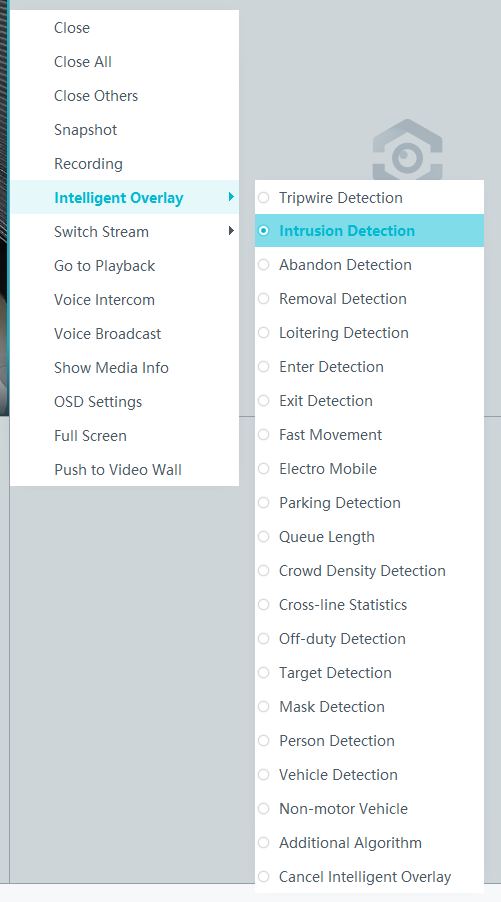
- Right-click a live video pane and choose Intelligent Overlay > Intrusion Detection, as shown in Figure 4-133. The real-time intelligent analysis result is superimposed on the video image.
- Viewing alarms
For details about how to view the latest or historical alarms, see Viewing Alarms (on the iClient S100).
Viewing Backend Alarms on the iClient S100
- View the behavior analysis task status.
- On the iClient S100 home page, choose .
- Right-click a device and choose Task Management.
- Set search criteria. You can click Advanced and set advanced search criteria.
After the setting, click Search. Then, you can view the behavior analysis task progress and status in the task list.
- View behavior analysis alarms on the Video Alarm page.
For details about how to view the latest or historical alarms, see Viewing Alarms (on the iClient S100).
Loitering Detection
Feature Description
Definition
The system automatically generates an alarm when a person is loitering in a specified area.
- Allows users to specify multiple polygonal detection areas.
- Allows users to specify an acceptable loitering duration (1s to 180s). When the loitering duration has elapsed, the system generates an alarm.
- Displays alarm information including the alarm type, occurrence time, duration, and object labeling.
Customer Benefits
The system automatically detects key information in video feeds through intelligent analysis, reducing labor costs and improving detection efficiency. Different intelligent analysis functions apply to different scenarios.
Application Scenario
Users can configure loitering detection for an area where loitering is not allowed.
Requirements
NE |
Version Requirement |
License Requirement |
Function |
|---|---|---|---|
HWT-IVS1800-D/HWT-IVS1800-E |
11.1.0 and later versions |
N/A |
Handles loitering alarms. |
iClient S100 |
V1.6.0 and later versions |
N/A |
Allows users to configure behavior analysis and alarm display in the camera web system. |
SDC |
Common perimeter detection: 8.0.0 and later versions (configurable on the LDU only in 8.2.0 and later versions) Enhanced perimeter detection: 9.0.0 and later versions |
N/A |
Supports behavior analysis (perimeter detection). |
Application Limitations
- Onsite conditions such as illumination and shooting angles affect the detection accuracy.
- This feature is supported only by cameras connected through HWSDK.
- Alarms can be triggered concurrently for a maximum of nine objects.
Feature Configuration (Based on Cameras)
Scenario Description
Table 4-114 describes the support for this feature in different client scenarios.
Client |
Feature Support |
Reference |
|---|---|---|
LDU |
Supported |
For details, see Procedure (on the LDU). |
Camera web system |
Supported |
Complete the configuration by referring to the product documentation of cameras. |
iClient S100 |
Supported |
For details, see Procedure (on the iClient S100). |
Prerequisites
- You have connected a camera that supports intelligent analysis.
- You have set the parameters listed in Setting Global Parameters (Configuring Frontend Behavior Analysis on the LDU) on the LDU.
- You have enabled behavior analysis for the camera and set global parameters on the iClient S100. For details, see Setting Global Parameters (Configuring Frontend Behavior Analysis on the iClient S100).
- Alarm linkage has been configured on the iClient S100. For details, see Configuring Alarm Linkage.
Procedure (on the LDU)
To view the configuration guide video, you can click in the upper left corner on the Configuration tab page, and scan the QR code.
- Log in to the LDU as the admin user. ( Logging In to the LDU)
- Click
 in the upper left corner.
 - Choose .
- Configure loitering detection, as shown in Figure 4-134.
Table 4-115 describes the key parameters and buttons.
Table 4-115 Parameter/Button descriptionType
Parameter/Button
Description
Detection Area
Detection Object
Type of objects that can be detected.
- Pedestrian
- Motor vehicle
- Non-motorized vehicle
No.
ID of a detection area. A maximum of four detection areas can be drawn.
Operation
Column containing the icons for drawing or deleting a detection area on the live video image.
Switch
Button for enabling or disabling a detection area.
Sound And Light Alarm
NOTE:The configurations of this function cannot be applied to other devices.
Audio switch/Twinkle switch
Indicates whether to produce audible alarms (playing audio files) or visual alarms (blinking light) when an alarm is triggered.
Audio Output
Audio file to be played when an alarm is triggered.
- You can directly use this function when an intelligent IR/white-light camera with intercom is used.
- To use this function when a camera other than the intelligent IR/white-light camera with intercom is used, you need to set audio parameters for the camera and connect the camera to an external audio output device.
Frequency
Number of times for playing an audio file when an alarm is triggered.
Twinkle Freq
Frequency at which the light blinks when an alarm is triggered. You can set this parameter to Low frequency, Medium frequency, or High frequency as required.
Currently, the visual alarm (blinking light) function is available only for intelligent IR/white-light cameras with intercom. You need to set light-related parameters.
Twinkle Time(s)
Period in which the light blinks when an alarm is triggered.
Alarm Settings
Alarm Sensitivity
Detection sensitivity of the system.
The value ranges from 1 to 100. A larger value indicates higher sensitivity.
Alarm Interval (s)
Interval at which alarms are checked, in seconds.
Pre-determined Alarm Position
Part of an object based on which detection is performed.
- Center: An object can be detected only when its central part enters the detection area.
- Top: An object can be detected only when its top part enters the detection area.
- Bottom: An object can be detected only when its bottom part enters the detection area.
The criteria for determining whether an object enters the detection area are related to Pre-determined Alarm Position. For example, if Pre-determined Alarm Position is set to Center, an alarm is triggered when the central part of an object enters the detection area.
- Configure an alert plan, as shown in Figure 4-135.
Table 4-116 describes the key parameters.
Table 4-116 Parameter/Button descriptionParameter/Button
Description
Add
Button for adding an alert plan. A maximum of eight alert plans are supported.
Delete All
Button for deleting all alert plans.
Button for enabling or disabling an alert plan. If you toggle on Status, the alert plan takes effect.
Day
Date on which an alert plan is executed.
The default value is Every Day.
Mode
Mode in which an alert plan is executed.
- Weekly
- One-off
- Configure an alarm linkage policy, as shown in Figure 4-136.
Table 4-117 describes the key parameters.
Table 4-117 Parameter descriptionType
Parameter
Description
Common Linkage
Display ID
Indicates whether to display the status icon of the camera that triggers an alarm on the live video viewing page. This function is used to notify users of an alarm generated by the current camera.
Full-Screen Alarm
Indicates whether to display alarms in full screen mode.
After this function is enabled, if a camera triggers an alarm and the live video viewing page is displayed on the LDU, the live video of the camera is played in full screen mode for 5s.
CAUTION:If another alarm is generated when live video is being played in full screen mode, this function is not triggered.
Send Email
- Indicates whether to send email notifications. After this function is enabled, the system sends an email to the configured email recipient when a service alarm is generated.
- You can click to customize the alarm email recipient and email body.
The email address for sending service alarms needs to be customized on the OMU portal.
For details about how to set the email address for sending service alarms, see How Do I Configure Connection to the SMTP Server?.
Recording
Channel
Camera to be linked to record video when an alarm is triggered.
Duration(s)
Customized recording duration. The value ranges from 5 to 3600, in seconds. You are advised to set this parameter to a value greater than or equal to 60 (default).
Triggered Snapshot
Channel
Camera to be linked to take snapshots when an alarm is triggered.
NOTE:If both snapshot taking and email sending are configured for alarm linkage, you can obtain both the alarm-triggered snapshots and the snapshots sent in the email.
Stop Recording
Channel
Camera to be linked to stop video recording when an alarm is triggered.
I/O Alarm
Channel ID
Alarm reporting channel.
Duration(s)
Customized alarm linkage duration.
The value ranges from 1 to 3600, in seconds.
NOTE:If the specified alarm linkage duration is different from the I/O alarm output duration configured in How Do I Connect Cables and Configure Alarm Input and Output Ports?, the shorter alarm duration is used.
For example, if the I/O alarm output duration is set to 20s and the alarm linkage duration is set to 30s, the actual alarm output duration is 20s.
Invoke Preset Position
Channel
Camera to be linked. When a service alarm is generated, the linked camera rotates to the specified preset position.
Before enabling preset position linkage, ensure that a preset position has been configured for the camera to be linked. For details about how to configure a preset position, see Feature Configuration.
Device
Name of the camera that is linked to a preset position.
Position
Preset position linked to the camera.

Procedure (on the iClient S100)
- On the iClient S100 home page, choose Maintenance Management > Smart Configuration.
- Select a camera for which you want to configure a behavior analysis policy.
- Choose and set parameters.
- Set parameters in the Parameter Settings area. Table 4-118 describes the parameters.
Table 4-118 Parameter description
Parameter
Description
Detection Target
Type of objects that can be detected. (This parameter is not involved when the behavior analysis type is abandoned object detection, removed object detection, or electric bike detection.)
- Pedestrian
- Motor vehicle
- Non-motorized vehicle
Alarm Detection Interval(s)
Interval at which the system checks for new alarms, in seconds. If any alarm is detected, the system reports the alarm to the iClient S100.
NOTE:To prevent a flood of alarms, the system reports only one alarm even if it detects multiple alarms within the specified interval.
Target Recognition Mode
Part of an object based on which detection is performed.
- centered: An object can be detected only when its central part enters the detection area.
- Bottom: An object can be detected only when its bottom part enters the detection area.
- tops: An object can be detected only when its top part enters the detection area.
Alarm Tolerance Time(s)
Duration for which an object can loiter in the detection area. If an object loiters in the detection area for a period longer than the specified duration, an alarm is generated.
Sensitivity
Detection sensitivity.
The value ranges from 1 to 100. A larger value indicates higher sensitivity.
- Set audible and visual alarm parameters. Table 4-119 describes the parameters.
Table 4-119 Audible and visual alarm parameters
Parameter
Description
Requirement on the Camera
Enable audio alarms
Indicates whether to produce audible alarms (play audio files) when an alarm is triggered.
- You can directly use this function when an intelligent IR/white-light camera with intercom is used.
- To use this function when a camera other than the intelligent IR/white-light camera with intercom is used, you need to set audio parameters for the camera and connect the camera to an external audio output device.
Audio file
Audio file to be played when an alarm is triggered.
To import an audio file to the iClient S100, choose Maintenance Management > Video Device > Device List on the home page, double-click the required camera that is connected to a device, and add an audio file on the Audio Channel tab page.
Playback times
Number of times for playing an audio file when an alarm is triggered.
Enable light flashing alarm
Indicates whether to produce visual alarms (blinking lights) when an alarm is triggered.
Currently, these functions are available when an intelligent IR/white-light camera with intercom is used. You need to set light-related parameters.
White light illuminator
Frequency at which the light blinks when an alarm is triggered. You can set this parameter to Low, Middle, High, or Steady on as required.
Flash duration (s)
Period in which the light blinks when an alarm is triggered.
- Set area parameters, as shown in Figure 4-137. Table 4-120 describes the parameters and buttons.
Table 4-120 Area settings
Parameter
Description
Area
Button for adding a detection area. A maximum of four detection areas can be configured for analyzing a type of behavior. A maximum of 10 detection areas can be configured for analyzing all types of behavior.
You can select and drag the detection area or change its shape and size.
Delete
Button for deleting a selected detection area.
Status
- If the parameter is toggled on, the frame of a detection area turns red and the detection takes effect.
- If the parameter is toggled off, the frame of a detection area turns white and the detection stops.
- Set plan parameters. Table 4-121 describes the parameters.
When the iClient S100 and an HWT-IVS1800 are in different time zones, the time set in the Plan Settings area refers to the time of the HWT-IVS1800.
Table 4-121 Plan settingsParameter/Button
Description
Add
Button for adding an alert plan. A maximum of eight alert plans are supported.
All Delete
Button for deleting all alert plans.
Start Time/End Time
Time segment during which alert is to be deployed.
Date
Date on which an alert plan is to be executed.
- Every day
- Monday to Sunday
Mode
Indicates whether to cyclically execute an alert plan.
- Weekly
- One-off
Operation
To delete the current alert plan, click
in the Operation column.
- Set parameters in the Parameter Settings area. Table 4-118 describes the parameters.
- Click Save.

Feature Configuration (Based on the HWT-IVS1800)
This feature applies only to PoC scenarios outside the Chinese mainland.
Scenario Description
- Table 4-122 describes the support for this feature in different client scenarios.
Client |
Feature Support |
Reference |
|---|---|---|
LDU |
Supported |
For details, see Procedure (on the LDU). |
iClient S100 |
Supported |
For details, see Procedure (on the iClient S100). |
- After local intelligence is enabled or an analysis task is created for a camera, do not modify the attributes of the camera. Otherwise, target recognition and video structuring tasks will become invalid, and you will need to delete and recreate the tasks.
Prerequisites
You have set the parameters listed in Public Configurations.
Procedure (on the LDU)
To view the configuration guide video, you can click in the upper left corner on the Configuration tab page, and scan the QR code.
- Log in to the LDU as the admin user. ( Logging In to the LDU)
- Right-click on the desktop and choose Intelligent Application.
- Choose Local Device Intelligence > Behavior Analysis > Loitering.
- Set basic loitering detection parameters, as shown in Figure 4-138.
Table 4-123 describes the parameters.
Table 4-123 Parameter descriptionParameter
Description
Button for enabling or disabling intrusion detection.
Detection Object
Type of objects to be detected. The options include Pedestrian and Motor vehicle. After you select a detection object type, the camera automatically reports an intrusion alarm upon detecting an object of the selected type.
No.
ID of a detection area. A maximum of four detection areas can be drawn.
Operation
Column containing the icons for drawing or deleting a detection area on the live video image.
You can draw detection areas based on the following rules:
- You are advised to draw lines clockwise. The lines you draw cannot cross each other or form a sharp acute angle. Otherwise, detection areas may fail to be drawn.
- Do not draw polygonal areas that overlap with each other. Otherwise, false negatives may occur.
Min Target
Minimum resolution of an object that can be detected, in pixels.
Max Target
Maximum resolution of a target that can be detected, in pixels.
Pre-determined Alarm Position
- Center: An object can be detected only when its central part enters the detection area.
- Top: An object can be detected only when its top part enters the detection area.
- Bottom: An object can be detected only when its bottom part enters the detection area.
Target Detection
Sensitivity for the system to trigger alarms when detecting objects in the detection area.
Higher sensitivity indicates a higher probability of triggering alarms and a higher false positive rate. The options are as follows:
- Lowest
- Low
- Lower
- Medium
- High (default)
Max Targets
Maximum number of objects that can be analyzed and processed in a detection area.
Alarm Interval(s)
Interval at which the system checks for new alarms.
To prevent a flood of alarms, the system reports only one alarm even if it detects multiple alarms within the specified interval.
- Configure an alert plan, as shown in Figure 4-139.
Table 4-124 describes the key parameters.
Table 4-124 Parameter descriptionParameter
Description
Add
Button for adding an alert plan.
Delete All
Button for deleting all alert plans.
Status
Indicates whether to enable an alert plan.
Start Time/End Time
Execution duration of the alert plan.
Date
Date on which an alert plan is to be executed.
- Every day
- Monday to Sunday
Mode
Indicates whether to cyclically execute an alert plan.
- Weekly
- One-off
Operation
Column containing the icon for deleting the alert plan.
- (Optional) Configure alarm linkage, as shown in Figure 4-140.
Table 4-125 describes the parameters.
Table 4-125 Parameter descriptionParameter
Description
Severity
Alarm severity. The default value is Minor. You do not need to set this parameter.
Channel
Camera to be linked to record video when an alarm is triggered.
When a camera triggers an alarm, the selected camera starts to record video.
Snapshot channel
Camera to be linked to take snapshots when an alarm is triggered.
When a camera triggers an alarm, the selected camera starts to take snapshots.
NOTE:If both snapshot taking and email sending are configured for alarm linkage, you can obtain both the alarm-triggered snapshot and the snapshot sent in the email.
- Click Apply.

Procedure (on the iClient S100)
- On the iClient S100 home page, choose .
- Right-click an HWT-IVS1800 and choose Task Management from the shortcut menu.
- Click New Task. In the New Task dialog box that is displayed, choose the desired behavior analysis task in the navigation tree on the left, and set related parameters, as shown in Figure 4-141.
Table 4-126 General parameters
Parameter
Description
Indicates whether to enable the current behavior analysis task.
Detection Object
Detection object.
- Pedestrian
- Motor vehicle
Alarm Interval(s)
Interval at which the system checks for new alarms, in seconds.
Dwell (s)
Time during which an object can loiter in the detection area. If an object loiters in the detection area for a period longer than the specified time, an alarm is generated.
This parameter is available only when you choose Loitering in the navigation tree.
The value ranges from 1 to 180 for loitering detection.
Reference
Part of an object based on which the detection is performed.
Target center: An object can be detected only when its central part enters the detection area.
Bottom center: An object can be detected only when its bottom part enters the detection area.
Top center: An object can be detected only when its top part enters the detection area.
For example, if this parameter is set to Top center, an alarm is generated only when the top part of the object is in the detection area.
Minimum detection target
Minimum resolution of an object that can be detected, in pixels.
Maximum detection target
Maximum resolution of an object that can be detected, in pixels.
Detection Area
Button for drawing a detection area. You can double-click the left mouse button to complete drawing.
You can draw detection areas based on the following rules:
- You are advised to draw lines clockwise. The lines you draw cannot cross each other or form a sharp acute angle. Otherwise, detection areas may fail to be drawn.
- Do not draw polygonal areas that overlap with each other. Otherwise, false negatives may occur.
- Click Save.
Feature Verification
On the LDU, the method of querying loitering detection alarms generated by cameras is the same as that of querying loitering detection alarms generated by the HWT-IVS1800.
Viewing Alarms (on the LDU)
- Log in to the LDU as the admin user. ( Logging In to the LDU)
- View alarms on the LDU.
- Viewing real-time alarms
- Right-click on the desktop and choose Live > Alarm List.
- Click and select the type of alarms to be viewed, as shown in Figure 4-142.
- Click an alarm card in the alarm list to view the alarm in full screen mode, as shown in Figure 4-143.
- By default, the alarm-triggered video is 10s long (5s before and 5s after the alarm time).
- If you click , the alarm list on the left stops refreshing the latest alarms. If you click again, the system refreshes all new alarms generated after the alarm refresh stops.
- Viewing historical alarms
- Right-click on the desktop and choose Retrieval.
- Choose Event Retrieval.
- View alarms, as shown in Figure 4-144.
You can click the Browsing Status icon to switch the alarm browsing mode. Alarms in the alarm center can be browsed in card or list mode.
- Viewing real-time alarms
Viewing Frontend Alarms on the iClient S100
- Viewing real-time intelligent analysis results
- On the iClient S100 home page, choose .
- Double-click an online camera in the Devices area or drag the online camera to a live video pane. Then you can view live video from this camera.
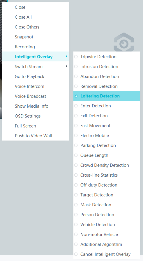
- Right-click a live video pane and choose Intelligent Overlay > Loitering Detection, as shown in Figure 4-145. The real-time intelligent analysis result is superimposed on the video image.
- Viewing alarms
For details about how to view the latest or historical alarms, see Viewing Alarms (on the iClient S100).
Viewing Backend Alarms on the iClient S100
- View the behavior analysis task status.
- On the iClient S100 home page, choose .
- Right-click a device and choose Task Management.
- Set search criteria. You can click Advanced and set advanced search criteria.
After the setting, click Search. Then, you can view the behavior analysis task progress and status in the task list.
- View behavior analysis alarms on the Video Alarm page.
For details about how to view the latest or historical alarms, see Viewing Alarms (on the iClient S100).
Abandoned Object Detection
Feature Description
Definition
The system automatically generates an alarm when an object is detected abandoned in a specified area. The system connects to cameras that support abandoned object detection to provide the following functions:
- Allows users to set analysis parameters, including detection areas (rectangle or polygon).
- Allows users to specify an acceptable object abandoned duration (10s to 300s). When the duration has elapsed, the system generates an alarm.
- Allows users to superimpose analysis results on live or recorded video images with a rectangular box (different objects are marked with different rectangular boxes) and label the object that triggers the alarm on video images.
- Allows users to record alarm information and trigger predefined alarm linkage actions.
Customer Benefits
The system automatically detects key information in video feeds through intelligent analysis, reducing labor costs and improving detection efficiency. Different intelligent analysis functions apply to different scenarios.
Application Scenario
- This feature is applicable to places that are alert to abandoned objects.
- This feature is applicable to scenarios where people may abandon their belongings, for example, shopping malls and campuses.
Requirements
NE |
Version Requirement |
License Requirement |
Function |
|---|---|---|---|
HWT-IVS1800-D/HWT-IVS1800-E |
11.1.0 and later versions |
N/A |
Handles abandoned object alarms. |
iClient S100 |
V1.6.0 and later versions |
N/A |
Allows users to configure behavior analysis and alarm display in the camera web system. |
SDC |
8.0.0 and later versions (configurable on the LDU only in 8.2.0 and later versions) |
N/A |
Supports abandoned object detection. |
Application Limitations
- Onsite conditions such as illumination and shooting angles affect the detection accuracy.
- This feature is supported only by cameras connected through HWSDK. In addition, this is a PoC feature of cameras, and can be used only for PoC testing on the platform.
- Alarms can be triggered concurrently for a maximum of nine objects.
Feature Configuration (Based on Cameras)
Scenario Description
Table 4-127 describes the support for this feature in different client scenarios.
Client |
Feature Support |
Reference |
|---|---|---|
LDU |
Supported |
For details, see Procedure (on the LDU). |
Camera web system |
Supported |
Complete the configuration by referring to the product documentation of cameras. |
iClient S100 |
Supported |
For details, see Procedure (on the iClient S100). |
Prerequisites
- You have connected a camera that supports intelligent analysis.
- You have set the parameters listed in Setting Global Parameters (Configuring Frontend Behavior Analysis on the LDU) on the LDU.
- You have enabled behavior analysis for the camera and set global parameters on the iClient S100. For details, see Setting Global Parameters (Configuring Frontend Behavior Analysis on the iClient S100).
- Alarm linkage has been configured on the iClient S100. For details, see Configuring Alarm Linkage.
Procedure (on the LDU)
To view the configuration guide video, you can click in the upper left corner on the Configuration tab page, and scan the QR code.
- Log in to the LDU as the admin user. ( Logging In to the LDU)
- Click
 in the upper left corner.
 - Choose .
- Configure abandoned object detection, as shown in Figure 4-146.
Table 4-128 describes the key parameters and buttons.
Table 4-128 Parameter/Button descriptionType
Parameter/Button
Description
Detection Area
No.
ID of a detection area. A maximum of four detection areas can be drawn.
Operation
Column containing the icons for drawing or deleting a detection area on the live video image.
Switch
Button for enabling or disabling a detection area.
Sound And Light Alarm
NOTE:The configurations of this function cannot be applied to other devices.
Audio switch/Twinkle switch
Indicates whether to produce audible alarms (playing audio files) or visual alarms (blinking light) when an alarm is triggered.
Audio Output
Audio file to be played when an alarm is triggered.
- You can directly use this function when an intelligent IR/white-light camera with intercom is used.
- To use this function when a camera other than the intelligent IR/white-light camera with intercom is used, you need to set audio parameters for the camera and connect the camera to an external audio output device.
Frequency
Number of times for playing an audio file when an alarm is triggered.
Twinkle Freq
Frequency at which the light blinks when an alarm is triggered. You can set this parameter to Low frequency, Medium frequency, or High frequency as required.
Currently, the visual alarm (blinking light) function is available only for intelligent IR/white-light cameras with intercom. You need to set light-related parameters.
Twinkle Time(s)
Period in which the light blinks when an alarm is triggered.
Alarm Settings
Alarm Sensitivity
Sensitivity for the system to detect abandoned objects.
The value ranges from 1 to 100. A larger value indicates higher sensitivity.
Alarm Interval (s)
Interval at which alarms are checked.
Pre-determined Alarm Position
Part of an object based on which detection is performed.
- Center: An object can be detected only when its central part enters the detection area.
- Top: An object can be detected only when its top part enters the detection area.
- Bottom: An object can be detected only when its bottom part enters the detection area.
The criteria for determining whether an object enters the detection area are related to Pre-determined Alarm Position. For example, if Pre-determined Alarm Position is set to Center, an alarm is triggered when the central part of an object enters the detection area.
- Configure an alert plan, as shown in Figure 4-147.
Table 4-129 describes the key parameters and buttons.
Table 4-129 Parameter/Button descriptionParameter/Button
Description
Add
Button for adding an alert plan. A maximum of eight alert plans are supported.
Delete All
Button for deleting all alert plans.
Button for enabling or disabling an alert plan. If you toggle on Status, the alert plan takes effect.
Day
Date on which an alert plan is executed.
The default value is Every Day.
Mode
Mode in which an alert plan is executed.
- Weekly
- One-off
- Configure an alarm linkage policy, as shown in Figure 4-148.
Table 4-130 describes the key parameters.
Table 4-130 Parameter descriptionType
Parameter
Description
Common Linkage
Display ID
Indicates whether to display the status icon of the camera that triggers an alarm on the live video viewing page. This function is used to notify users of an alarm generated by the current camera.
Full-Screen Alarm
Indicates whether to display alarms in full screen mode.
After this function is enabled, if a camera triggers an alarm and the live video viewing page is displayed on the LDU, the live video of the camera is played in full screen mode for 5s.
CAUTION:If another alarm is generated when live video is being played in full screen mode, this function is not triggered.
Send Email
- Indicates whether to send email notifications. After this function is enabled, the system sends an email to the configured email recipient when a service alarm is generated.
- You can click to customize the alarm email recipient and email body.
The email address for sending service alarms needs to be customized on the OMU portal.
For details about how to set the email address for sending service alarms, see How Do I Configure Connection to the SMTP Server?.
Recording
Channel
Camera to be linked to record video when an alarm is triggered.
Duration(s)
Customized recording duration. The value ranges from 5 to 3600, in seconds. You are advised to set this parameter to a value greater than or equal to 60 (default).
Triggered Snapshot
Channel
Camera to be linked to take snapshots when an alarm is triggered.
NOTE:If both snapshot taking and email sending are configured for alarm linkage, you can obtain both the alarm-triggered snapshots and the snapshots sent in the email.
Stop Recording
Channel
Camera to be linked to stop video recording when an alarm is triggered.
I/O Alarm
Channel ID
Alarm reporting channel.
Duration(s)
Customized alarm linkage duration.
The value ranges from 1 to 3600, in seconds.
NOTE:If the specified alarm linkage duration is different from the I/O alarm output duration configured in How Do I Connect Cables and Configure Alarm Input and Output Ports?, the shorter alarm duration is used.
For example, if the I/O alarm output duration is set to 20s and the alarm linkage duration is set to 30s, the actual alarm output duration is 20s.
Invoke Preset Position
Channel
Camera to be linked. When a service alarm is generated, the linked camera rotates to the specified preset position.
Before enabling preset position linkage, ensure that a preset position has been configured for the camera to be linked. For details about how to configure a preset position, see Feature Configuration.
Device
Name of the camera that is linked to a preset position.
Position
Preset position linked to the camera.

Procedure (on the iClient S100)
- On the iClient S100 home page, choose Maintenance Management > Smart Configuration.
- Select a camera for which you want to configure a behavior analysis policy.
- Choose and set related parameters.
- Set parameters in the Parameter Settings area. Table 4-131 describes the parameters.
Table 4-131 Parameter description
Parameter
Description
Detection Target
Type of objects that can be detected. (This parameter is not involved when the behavior analysis type is abandoned object detection, removed object detection, or electric bike detection.)
- Pedestrian
- Motor vehicle
- Non-motorized vehicle
Alarm Detection Interval(s)
Interval at which the system checks for new alarms, in seconds. If any alarm is detected, the system reports the alarm to the iClient S100.
NOTE:To prevent a flood of alarms, the system reports only one alarm even if it detects multiple alarms within the specified interval.
Target Recognition Mode
Part of an object based on which detection is performed.
- centered: An object can be detected only when its central part enters the detection area.
- Bottom: An object can be detected only when its bottom part enters the detection area.
- tops: An object can be detected only when its top part enters the detection area.
Leftover Tolerance Time(s)
Duration during which an object can be left in the detection area. If an object is left in the detection area for a period longer than the specified time, an alarm is generated.
Sensitivity
Detection sensitivity.
The value ranges from 1 to 100. A larger value indicates higher sensitivity.
- Set audible and visual alarm parameters. Table 4-132 describes the parameters.
Table 4-132 Audible and visual alarm parameters
Parameter
Description
Requirement on the Camera
Enable audio alarms
Indicates whether to produce audible alarms (play audio files) when an alarm is triggered.
- You can directly use this function when an intelligent IR/white-light camera with intercom is used.
- To use this function when a camera other than the intelligent IR/white-light camera with intercom is used, you need to set audio parameters for the camera and connect the camera to an external audio output device.
Audio file
Audio file to be played when an alarm is triggered.
To import an audio file to the iClient S100, choose Maintenance Management > Video Device > Device List on the home page, double-click the required camera that is connected to a device, and add an audio file on the Audio Channel tab page.
Playback times
Number of times for playing an audio file when an alarm is triggered.
Enable light flashing alarm
Indicates whether to produce visual alarms (blinking lights) when an alarm is triggered.
Currently, these functions are available when an intelligent IR/white-light camera with intercom is used. You need to set light-related parameters.
White light illuminator
Frequency at which the light blinks when an alarm is triggered. You can set this parameter to Low, Middle, High, or Steady on as required.
Flash duration (s)
Period in which the light blinks when an alarm is triggered.
- Set area parameters, as shown in Figure 4-149. Table 4-133 describes the parameters and buttons.
Table 4-133 Area settings
Parameter/Button
Description
Area
Button for adding a detection area. A maximum of four detection areas can be configured for analyzing a type of behavior. A maximum of 10 detection areas can be configured for analyzing all types of behavior.
You can select and drag the detection area or change its shape and size.
Delete
Button for deleting a selected detection area.
Status
- If the parameter is toggled on, the frame of a detection area turns red and the detection takes effect.
- If the parameter is toggled off, the frame of a detection area turns white and the detection stops.
- Set plan parameters. Table 4-134 describes the parameters.
When the iClient S100 and an HWT-IVS1800 are in different time zones, the time set in the Plan Settings area refers to the time of the HWT-IVS1800.
Table 4-134 Plan settingsParameter/Button
Description
Add
Button for adding an alert plan. A maximum of eight alert plans are supported.
All Delete
Button for deleting all alert plans.
Start Time/End Time
Time segment during which alert is to be deployed.
Date
Date on which an alert plan is to be executed.
- Every day
- Monday to Sunday
Mode
Indicates whether to cyclically execute an alert plan.
- Weekly
- One-off
Operation
To delete the current alert plan, click
in the Operation column.
- Set parameters in the Parameter Settings area. Table 4-131 describes the parameters.
- Click Save.

Feature Verification
Viewing Alarms (on the LDU)
- Log in to the LDU as the admin user. ( Logging In to the LDU)
- View alarms on the LDU.
- Viewing real-time alarms
- Right-click on the desktop and choose Live > Alarm List.
- Click and select the type of alarms to be viewed, as shown in Figure 4-150.
- Click an alarm card in the alarm list to view the alarm in full screen mode, as shown in Figure 4-151.
- By default, the alarm-triggered video is 10s long (5s before and 5s after the alarm time).
- If you click , the alarm list on the left stops refreshing the latest alarms. If you click again, the system refreshes all new alarms generated after the alarm refresh stops.
- Viewing historical alarms
- Right-click on the desktop and choose Retrieval.
- Choose Event Retrieval.
- View alarms, as shown in Figure 4-152.
You can click the Browsing Status icon to switch the alarm browsing mode. Alarms in the alarm center can be browsed in card or list mode.
- Viewing real-time alarms
Viewing Alarms (on the iClient S100)
- Viewing real-time intelligent analysis results
- On the iClient S100 home page, choose .
- Double-click an online camera in the Devices area or drag the online camera to a live video pane. Then you can view live video from this camera.
- Right-click a live video pane and choose Intelligent Overlay > Abandon Detection, as shown in Figure 4-153. The real-time intelligent analysis result is superimposed on the video image.
- Viewing alarms
For details about how to view the latest or historical alarms, see Viewing Alarms (on the iClient S100).
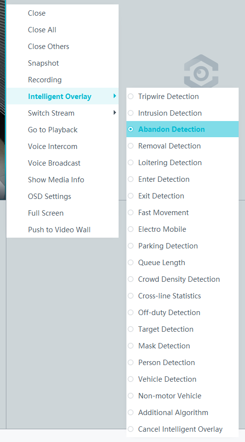
Removed Object Detection
Feature Description
Definition
The system automatically generates an alarm when an object is detected removed from a specified area. The system connects to cameras that support removed object detection to provide the following functions:
- Allows users to set analysis parameters, including detection areas (rectangle or polygon).
- Allows users to set the duration (10s to 300s) when an object is removable. When the duration has elapsed, the system generates an alarm.
- Allows users to superimpose analysis results on live or recorded video images with a rectangular box (different objects are marked with different rectangular boxes) and label the object that triggers the alarm on video images.
- Allows users to record alarm information and trigger predefined alarm linkage actions.
Customer Benefits
The system automatically detects key information in video feeds through intelligent analysis, reducing labor costs and improving detection efficiency. Different intelligent analysis functions apply to different scenarios.
Application Scenario
This feature is applicable to areas that are alert to object removal, for example, museums and exhibition halls.
Requirements
NE |
Version Requirement |
License Requirement |
Function |
|---|---|---|---|
HWT-IVS1800-D/HWT-IVS1800-E |
11.1.0 and later versions |
N/A |
Handles removed object alarms. |
iClient S100 |
V1.6.0 and later versions |
N/A |
Allows users to configure behavior analysis and alarm display in the camera web system. |
SDC |
8.0.0 and later versions (configurable on the LDU only in 8.2.0 and later versions) |
N/A |
Supports removed object detection. |
Application Limitations
- Onsite conditions such as illumination and shooting angles affect the detection accuracy.
- This feature is supported only by cameras connected through HWSDK. In addition, this is a PoC feature of cameras, and can be used only for PoC testing on the platform.
- Alarms can be triggered concurrently for a maximum of nine objects.
Feature Configuration (Based on Cameras)
Scenario Description
Table 4-135 describes the support for this feature in different client scenarios.
Client |
Feature Support |
Reference |
|---|---|---|
LDU |
Supported |
For details, see Procedure (on the LDU). |
Camera web system |
Supported |
Complete the configuration by referring to the product documentation of cameras. |
iClient S100 |
Supported |
For details, see Procedure (on the iClient S100). |
Prerequisites
- You have connected a camera that supports intelligent analysis.
- You have set the parameters listed in Setting Global Parameters (Configuring Frontend Behavior Analysis on the LDU) on the LDU.
- You have enabled behavior analysis for the camera and set global parameters on the iClient S100. For details, see Setting Global Parameters (Configuring Frontend Behavior Analysis on the iClient S100).
- Alarm linkage has been configured on the iClient S100. For details, see Configuring Alarm Linkage.
Procedure (on the LDU)
To view the configuration guide video, you can click in the upper left corner on the Configuration tab page, and scan the QR code.
- Log in to the LDU as the admin user. ( Logging In to the LDU)
- Click
 in the upper left corner.
 - Choose .
- Configure removed object detection, as shown in Figure 4-154.
Table 4-136 describes the key parameters and buttons.
Table 4-136 Parameter/Button descriptionType
Parameter/Button
Description
Detection Area
No.
ID of a detection area. A maximum of four detection areas can be drawn.
Operation
Column containing the icons for drawing or deleting a detection area on the live video image.
Switch
Button for enabling or disabling a detection area.
Sound And Light Alarm
NOTE:The configurations of this function cannot be applied to other devices.
Audio switch/Twinkle switch
Indicates whether to produce audible alarms (playing audio files) or visual alarms (blinking light) when an alarm is triggered.
Audio Output
Audio file to be played when an alarm is triggered.
- You can directly use this function when an intelligent IR/white-light camera with intercom is used.
- To use this function when a camera other than the intelligent IR/white-light camera with intercom is used, you need to set audio parameters for the camera and connect the camera to an external audio output device.
Frequency
Number of times for playing an audio file when an alarm is triggered.
Twinkle Freq
Frequency at which the light blinks when an alarm is triggered. You can set this parameter to Low frequency, Medium frequency, or High frequency as required.
Currently, the visual alarm (blinking light) function is available only for intelligent IR/white-light cameras with intercom. You need to set light-related parameters.
Twinkle Time(s)
Period in which the light blinks when an alarm is triggered.
Alarm Settings
Alarm Sensitivity
Sensitivity for the system to detect abandoned objects.
The value ranges from 1 to 100. A larger value indicates higher sensitivity.
Alarm Interval (s)
Interval at which alarms are checked.
Pre-determined Alarm Position
Part of an object based on which detection is performed.
- Center: An object can be detected only when its central part enters the detection area.
- Top: An object can be detected only when its top part enters the detection area.
- Bottom: An object can be detected only when its bottom part enters the detection area.
The criteria for determining whether an object enters the detection area are related to Pre-determined Alarm Position. For example, if Pre-determined Alarm Position is set to Center, an alarm is triggered when the central part of an object enters the detection area.
- Configure an alert plan, as shown in Figure 4-155.
Table 4-137 describes the key parameters and buttons.
Table 4-137 Parameter/Button descriptionParameter/Button
Description
Add
Button for adding an alert plan. A maximum of eight alert plans are supported.
Delete All
Button for deleting all alert plans.
Button for enabling or disabling an alert plan. If you toggle on Status, the alert plan takes effect.
Day
Date on which an alert plan is executed.
The default value is Every Day.
Mode
Mode in which an alert plan is executed.
- Weekly
- One-off
- Configure an alarm linkage policy, as shown in Figure 4-156.
Table 4-138 describes the key parameters.
Table 4-138 Parameter descriptionType
Parameter
Description
Common Linkage
Display ID
Indicates whether to display the status icon of the camera that triggers an alarm on the live video viewing page. This function is used to notify users of an alarm generated by the current camera.
Full-Screen Alarm
Indicates whether to display alarms in full screen mode.
After this function is enabled, if a camera triggers an alarm and the live video viewing page is displayed on the LDU, the live video of the camera is played in full screen mode for 5s.
CAUTION:If another alarm is generated when live video is being played in full screen mode, this function is not triggered.
Send Email
- Indicates whether to send email notifications. After this function is enabled, the system sends an email to the configured email recipient when a service alarm is generated.
- You can click to customize the alarm email recipient and email body.
The email address for sending service alarms needs to be customized on the OMU portal.
For details about how to set the email address for sending service alarms, see How Do I Configure Connection to the SMTP Server?.
Recording
Channel
Camera to be linked to record video when an alarm is triggered.
Duration(s)
Customized recording duration. The value ranges from 5 to 3600, in seconds. You are advised to set this parameter to a value greater than or equal to 60 (default).
Triggered Snapshot
Channel
Camera to be linked to take snapshots when an alarm is triggered.
NOTE:If both snapshot taking and email sending are configured for alarm linkage, you can obtain both the alarm-triggered snapshots and the snapshots sent in the email.
Stop Recording
Channel
Camera to be linked to stop video recording when an alarm is triggered.
I/O Alarm
Channel ID
Alarm reporting channel.
Duration(s)
Customized alarm linkage duration.
The value ranges from 1 to 3600, in seconds.
NOTE:If the specified alarm linkage duration is different from the I/O alarm output duration configured in How Do I Connect Cables and Configure Alarm Input and Output Ports?, the shorter alarm duration is used.
For example, if the I/O alarm output duration is set to 20s and the alarm linkage duration is set to 30s, the actual alarm output duration is 20s.
Invoke Preset Position
Channel
Camera to be linked. When a service alarm is generated, the linked camera rotates to the specified preset position.
Before enabling preset position linkage, ensure that a preset position has been configured for the camera to be linked. For details about how to configure a preset position, see Feature Configuration.
Device
Name of the camera that is linked to a preset position.
Position
Preset position linked to the camera.

Procedure (on the iClient S100)
- On the iClient S100 home page, choose Maintenance Management > Smart Configuration.
- Select a camera for which you want to configure a behavior analysis policy.
- Choose and set related parameters.
- Set parameters in the Parameter Settings area. Table 4-139 describes the parameters.
Table 4-139 Parameter description
Parameter
Description
Detection Target
Type of objects that can be detected. (This parameter is not involved when the behavior analysis type is abandoned object detection, removed object detection, or electric bike detection.)
- Pedestrian
- Motor vehicle
- Non-motorized vehicle
Alarm Detection Interval(s)
Interval at which the system checks for new alarms, in seconds. If any alarm is detected, the system reports the alarm to the iClient S100.
NOTE:To prevent a flood of alarms, the system reports only one alarm even if it detects multiple alarms within the specified interval.
Target Recognition Mode
Part of an object based on which detection is performed.
- centered: An object can be detected only when its central part enters the detection area.
- Bottom: An object can be detected only when its bottom part enters the detection area.
- tops: An object can be detected only when its top part enters the detection area.
Sensitivity
Detection sensitivity.
The value ranges from 1 to 100. A larger value indicates higher sensitivity.
- Set audible and visual alarm parameters. Table 4-140 describes the parameters.
Table 4-140 Audible and visual alarm parameters
Parameter
Description
Requirement on the Camera
Enable audio alarms
Indicates whether to produce audible alarms (play audio files) when an alarm is triggered.
- You can directly use this function when an intelligent IR/white-light camera with intercom is used.
- To use this function when a camera other than the intelligent IR/white-light camera with intercom is used, you need to set audio parameters for the camera and connect the camera to an external audio output device.
Audio file
Audio file to be played when an alarm is triggered.
To import an audio file to the iClient S100, choose Maintenance Management > Video Device > Device List on the home page, double-click the required camera that is connected to a device, and add an audio file on the Audio Channel tab page.
Playback times
Number of times for playing an audio file when an alarm is triggered.
Enable light flashing alarm
Indicates whether to produce visual alarms (blinking lights) when an alarm is triggered.
Currently, these functions are available when an intelligent IR/white-light camera with intercom is used. You need to set light-related parameters.
White light illuminator
Frequency at which the light blinks when an alarm is triggered. You can set this parameter to Low, Middle, High, or Steady on as required.
Flash duration (s)
Period in which the light blinks when an alarm is triggered.
- Set area parameters, as shown in Figure 4-157. Table 4-141 describes the parameters.
Table 4-141 Area settings
Parameter
Description
Area
Button for adding a detection area. A maximum of four detection areas can be configured for analyzing a type of behavior. A maximum of 10 detection areas can be configured for analyzing all types of behavior.
You can select and drag the detection area or change its shape and size.
Delete
Button for deleting a selected detection area.
Status
- If the parameter is toggled on, the frame of a detection area turns red and the detection takes effect.
- If the parameter is toggled off, the frame of a detection area turns white and the detection stops.
- Set plan parameters. Table 4-142 describes the parameters.
When the iClient S100 and an HWT-IVS1800 are in different time zones, the time set in the Plan Settings area refers to the time of the HWT-IVS1800.
Table 4-142 Plan settingsParameter/Button
Description
Add
Button for adding an alert plan. A maximum of eight alert plans are supported.
All Delete
Button for deleting all alert plans.
Start Time/End Time
Time segment during which alert is to be deployed.
Date
Date on which an alert plan is to be executed.
- Every day
- Monday to Sunday
Mode
Indicates whether to cyclically execute an alert plan.
- Weekly
- One-off
Operation
To delete the current alert plan, click
in the Operation column.
- Set parameters in the Parameter Settings area. Table 4-139 describes the parameters.
- Click Save.

Feature Verification
Viewing Alarms (on the LDU)
- Log in to the LDU as the admin user. ( Logging In to the LDU)
- View alarms on the LDU.
- Viewing real-time alarms
- Right-click on the desktop and choose Live > Alarm List.
- Click and select the type of alarms to be viewed, as shown in Figure 4-158.
- Click an alarm card in the alarm list to view the alarm in full screen mode, as shown in Figure 4-159.
- By default, the alarm-triggered video is 10s long (5s before and 5s after the alarm time).
- If you click , the alarm list on the left stops refreshing the latest alarms. If you click again, the system refreshes all new alarms generated after the alarm refresh stops.
- Viewing historical alarms
- Right-click on the desktop and choose Retrieval.
- Choose Event Retrieval.
- View alarms, as shown in Figure 4-160.
You can click the Browsing Status icon to switch the alarm browsing mode. Alarms in the alarm center can be browsed in card or list mode.
- Viewing real-time alarms
Viewing Alarms (on the iClient S100)
- Viewing real-time intelligent analysis results
- On the iClient S100 home page, choose .
- Double-click an online camera in the Devices area or drag the online camera to a live video pane. Then you can view live video from this camera.
- Right-click a live video pane and choose Intelligent Overlay > Removal Detection, as shown in Figure 4-161. The real-time intelligent analysis result is superimposed on the video image.
- Viewing alarms
For details about how to view the latest or historical alarms, see Viewing Alarms (on the iClient S100).
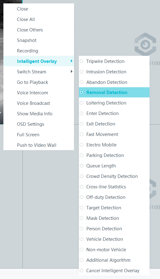
Tripwire Crossing Detection
Feature Description
Definition
The system generates an alarm when an object is detected crossing a tripwire from the specified direction in a specified area. The system connects to cameras that support tripwire crossing detection to provide the following functions:
- Allows users to set tripwires and directions.
- Detects and distinguishes multiple objects that cross tripwires, and generates alarms.
- Allows users to superimpose analysis results on live or recorded video images with a rectangular box (different objects are marked with different rectangular boxes) and label the object that triggers the alarm on video images.
- Allows users to record alarm information and trigger predefined alarm linkage actions.
Customer Benefits
The system automatically detects key information in video feeds through intelligent analysis, reducing labor costs and improving detection efficiency. Different intelligent analysis functions apply to different scenarios.
Application Scenario
This feature is applicable to places where irrelevant persons are not allowed to cross specified lines.
Requirements
NE |
Version Requirement |
License Requirement |
Function |
|---|---|---|---|
HWT-IVS1800-D/HWT-IVS1800-E |
11.1.0 and later versions |
N/A |
Handles tripwire crossing alarms. |
iClient S100 |
V1.6.0 and later versions |
N/A |
Allows users to configure behavior analysis and alarm display in the camera web system. |
SDC |
Common perimeter detection: 8.0.0 and later versions (configurable on the LDU only in 8.2.0 and later versions) Enhanced perimeter detection: 9.0.0 and later versions |
N/A |
Supports behavior analysis (perimeter detection). Enhanced perimeter detection is recommended. |
Application Limitations
- Onsite conditions such as illumination and shooting angles affect the detection accuracy.
- This feature is supported only by cameras connected through HWSDK.
- Alarms can be triggered concurrently for a maximum of nine objects.
Feature Configuration (Based on Cameras)
Scenario Description
Table 4-143 describes the support for this feature in different client scenarios.
Client |
Feature Support |
Reference |
|---|---|---|
LDU |
Supported |
For details, see Procedure (on the LDU). |
Camera web system |
Supported |
Complete the configuration by referring to the product documentation of cameras. |
iClient S100 |
Supported |
For details, see Procedure (on the iClient S100). |
Prerequisites
- You have connected a camera that supports intelligent analysis.
- You have set the parameters listed in Setting Global Parameters (Configuring Frontend Behavior Analysis on the LDU) on the LDU.
- You have enabled behavior analysis for the camera and set global parameters on the iClient S100. For details, see Setting Global Parameters (Configuring Frontend Behavior Analysis on the iClient S100).
- Alarm linkage has been configured on the iClient S100. For details, see Configuring Alarm Linkage.
Procedure (on the LDU)
To view the configuration guide video, you can click in the upper left corner on the Configuration tab page, and scan the QR code.
- Log in to the LDU as the admin user. ( Logging In to the LDU)
- Click
 in the upper left corner.
 - Choose .
- Configure tripwire crossing detection, as shown in Figure 4-162.
Table 4-144 describes the key parameters and buttons.
Table 4-144 Parameter/Button descriptionType
Parameter/Button
Description
Detection Area
Detection Object
Type of objects that can be detected.
- Pedestrian
- Motor vehicle
- Non-motorized vehicle
No.
ID of a detection area. A maximum of four detection areas can be drawn.
Operation
Column containing the icons for drawing or deleting a detection area on the live video image.
Switch
Button for enabling or disabling a detection area.
Sound And Light Alarm
NOTE:The configurations of this function cannot be applied to other devices.
Audio switch/Twinkle switch
Indicates whether to produce audible alarms (playing audio files) or visual alarms (blinking light) when an alarm is triggered.
Audio Output
Audio file to be played when an alarm is triggered.
- You can directly use this function when an intelligent IR/white-light camera with intercom is used.
- To use this function when a camera other than the intelligent IR/white-light camera with intercom is used, you need to set audio parameters for the camera and connect the camera to an external audio output device.
Frequency
Number of times for playing an audio file when an alarm is triggered.
Twinkle Freq
Frequency at which the light blinks when an alarm is triggered. You can set this parameter to Low frequency, Medium frequency, or High frequency as required.
Currently, the visual alarm (blinking light) function is available only for intelligent IR/white-light cameras with intercom. You need to set light-related parameters.
Twinkle Time(s)
Period in which the light blinks when an alarm is triggered.
Alarm Settings
Alarm Sensitivity
Detection sensitivity of the system.
The value ranges from 1 to 100. A larger value indicates higher sensitivity.
Alarm Interval (s)
Interval at which alarms are checked, in seconds.
Pre-determined Alarm Position
Part of an object based on which detection is performed.
- Center: An object can be detected only when its central part enters the detection area.
- Top: An object can be detected only when its top part enters the detection area.
- Bottom: An object can be detected only when its bottom part enters the detection area.
The criteria for determining whether an object enters the detection area are related to Pre-determined Alarm Position. For example, if Pre-determined Alarm Position is set to Center, an alarm is triggered when the central part of an object enters the detection area.
- Configure an alert plan, as shown in Figure 4-163.
Table 4-145 describes the key parameters.
Table 4-145 Parameter/Button descriptionParameter/Button
Description
Add
Button for adding an alert plan. A maximum of eight alert plans are supported.
Delete All
Button for deleting all alert plans.
Button for enabling or disabling an alert plan. If you toggle on Status, the alert plan takes effect.
Day
Date on which an alert plan is executed.
The default value is Every Day.
Mode
Mode in which an alert plan is executed.
- Weekly
- One-off
- Configure an alarm linkage policy, as shown in Figure 4-164.
Table 4-146 describes the key parameters.
Table 4-146 Parameter descriptionType
Parameter
Description
Common Linkage
Display ID
Indicates whether to display the status icon of the camera that triggers an alarm on the live video viewing page. This function is used to notify users of an alarm generated by the current camera.
Full-Screen Alarm
Indicates whether to display alarms in full screen mode.
After this function is enabled, if a camera triggers an alarm and the live video viewing page is displayed on the LDU, the live video of the camera is played in full screen mode for 5s.
CAUTION:If another alarm is generated when live video is being played in full screen mode, this function is not triggered.
Send Email
- Indicates whether to send email notifications. After this function is enabled, the system sends an email to the configured email recipient when a service alarm is generated.
- You can click to customize the alarm email recipient and email body.
The email address for sending service alarms needs to be customized on the OMU portal.
For details about how to set the email address for sending service alarms, see How Do I Configure Connection to the SMTP Server?.
Recording
Channel
Camera to be linked to record video when an alarm is triggered.
Duration(s)
Customized recording duration. The value ranges from 5 to 3600, in seconds. You are advised to set this parameter to a value greater than or equal to 60 (default).
Triggered Snapshot
Channel
Camera to be linked to take snapshots when an alarm is triggered.
NOTE:If both snapshot taking and email sending are configured for alarm linkage, you can obtain both the alarm-triggered snapshots and the snapshots sent in the email.
Stop Recording
Channel
Camera to be linked to stop video recording when an alarm is triggered.
I/O Alarm
Channel ID
Alarm reporting channel.
Duration(s)
Customized alarm linkage duration.
The value ranges from 1 to 3600, in seconds.
NOTE:If the specified alarm linkage duration is different from the I/O alarm output duration configured in How Do I Connect Cables and Configure Alarm Input and Output Ports?, the shorter alarm duration is used.
For example, if the I/O alarm output duration is set to 20s and the alarm linkage duration is set to 30s, the actual alarm output duration is 20s.
Invoke Preset Position
Channel
Camera to be linked. When a service alarm is generated, the linked camera rotates to the specified preset position.
Before enabling preset position linkage, ensure that a preset position has been configured for the camera to be linked. For details about how to configure a preset position, see Feature Configuration.
Device
Name of the camera that is linked to a preset position.
Position
Preset position linked to the camera.

Procedure (on the iClient S100)
- On the iClient S100 home page, choose Maintenance Management > Smart Configuration.
- Select a camera for which you want to configure a behavior analysis policy.
- Choose and set related parameters.
- Set parameters in the Parameter Settings area. Table 4-147 describes the parameters.
Table 4-147 Parameter description
Parameter
Description
Detection Target
Type of objects that can be detected. (This parameter is not involved when the behavior analysis type is abandoned object detection, removed object detection, or electric bike detection.)
- Pedestrian
- Motor vehicle
- Non-motorized vehicle
Alarm Detection Interval(s)
Interval at which the system checks for new alarms, in seconds. If any alarm is detected, the system reports the alarm to the iClient S100.
NOTE:To prevent a flood of alarms, the system reports only one alarm even if it detects multiple alarms within the specified interval.
Target Recognition Mode
Part of an object based on which detection is performed.
- centered: An object can be detected only when its central part enters the detection area.
- Bottom: An object can be detected only when its bottom part enters the detection area.
- tops: An object can be detected only when its top part enters the detection area.
Sensitivity
Detection sensitivity.
The value ranges from 1 to 100. A larger value indicates higher sensitivity.
- Set audible and visual alarm parameters. Table 4-148 describes the parameters.
Table 4-148 Audible and visual alarm parameters
Parameter
Description
Requirement on the Camera
Enable audio alarms
Indicates whether to produce audible alarms (play audio files) when an alarm is triggered.
- You can directly use this function when an intelligent IR/white-light camera with intercom is used.
- To use this function when a camera other than the intelligent IR/white-light camera with intercom is used, you need to set audio parameters for the camera and connect the camera to an external audio output device.
Audio file
Audio file to be played when an alarm is triggered.
To import an audio file to the iClient S100, choose Maintenance Management > Video Device > Device List on the home page, double-click the required camera that is connected to a device, and add an audio file on the Audio Channel tab page.
Playback times
Number of times for playing an audio file when an alarm is triggered.
Enable light flashing alarm
Indicates whether to produce visual alarms (blinking lights) when an alarm is triggered.
Currently, these functions are available when an intelligent IR/white-light camera with intercom is used. You need to set light-related parameters.
White light illuminator
Frequency at which the light blinks when an alarm is triggered. You can set this parameter to Low, Middle, High, or Steady on as required.
Flash duration (s)
Period in which the light blinks when an alarm is triggered.
- Set area parameters, as shown in Figure 4-165. Table 4-149 describes the parameters and buttons.
Table 4-149 Area settings
Parameter
Description
Detection Line
Button for adding a detection line. A maximum of four detection lines are supported.
You can select and drag a detection line to change its location or change its length.
Delete
Button for deleting a selected detection line.
Direction
Specified direction in which a pedestrian crosses the detection line. The options are as follows: A<->B, A->B, and B->A
Status
- If the parameter is toggled on, the detection line turns red and the detection takes effect.
- If the parameter is toggled off, the detection line turns white and the detection stops.
- Set plan parameters. Table 4-150 describes the parameters.
When the iClient S100 and an HWT-IVS1800 are in different time zones, the time set in the Plan Settings area refers to the time of the HWT-IVS1800.
Table 4-150 Plan settingsParameter/Button
Description
Add
Button for adding an alert plan. A maximum of eight alert plans are supported.
All Delete
Button for deleting all alert plans.
Start Time/End Time
Time segment during which alert is to be deployed.
Date
Date on which an alert plan is to be executed.
- Every day
- Monday to Sunday
Mode
Indicates whether to cyclically execute an alert plan.
- Weekly
- One-off
Operation
To delete the current alert plan, click
in the Operation column.
- Set parameters in the Parameter Settings area. Table 4-147 describes the parameters.
- Click Save.

Feature Configuration (Based on the HWT-IVS1800)
This feature applies only to PoC scenarios outside the Chinese mainland.
Scenario Description
- Table 4-151 describes the support for this feature in different client scenarios.
Client |
Feature Support |
Reference |
|---|---|---|
LDU |
Supported |
For details, see Procedure (on the LDU). |
iClient S100 |
Supported |
For details, see Procedure (on the iClient S100). |
- After local intelligence is enabled or an analysis task is created for a camera, do not modify the attributes of the camera. Otherwise, target recognition and video structuring tasks will become invalid, and you will need to delete and recreate the tasks.
Prerequisites
You have set the parameters listed in Public Configurations.
Procedure (on the LDU)
To view the configuration guide video, you can click in the upper left corner on the Configuration tab page, and scan the QR code.
- Log in to the LDU as the admin user. ( Logging In to the LDU)
- Right-click on the desktop and choose Intelligent Application.
- Choose Local Device Intelligence > Behavior Analysis > Tripwire.
- Set basic parameters of tripwire crossing detection, as shown in Figure 4-166.
Table 4-152 describes the parameters.
Table 4-152 Parameter descriptionParameter
Description
Button for enabling or disabling intrusion detection.
Detection Object
Type of objects to be detected. The options include Pedestrian and Motor vehicle. After you select a detection object type, the camera automatically reports an intrusion alarm upon detecting an object of the selected type.
No.
ID of a detection area. A maximum of four detection areas can be drawn.
Operation
Column containing the icons for drawing or deleting a detection area on the live video image.
You can draw detection areas based on the following rules:
- You are advised to draw lines clockwise. The lines you draw cannot cross each other or form a sharp acute angle. Otherwise, detection areas may fail to be drawn.
- Do not draw polygonal areas that overlap with each other. Otherwise, false negatives may occur.
Min Target
Minimum resolution of an object that can be detected, in pixels.
Max Target
Maximum resolution of a target that can be detected, in pixels.
Pre-determined Alarm Position
- Center: An object can be detected only when its central part enters the detection area.
- Top: An object can be detected only when its top part enters the detection area.
- Bottom: An object can be detected only when its bottom part enters the detection area.
Target Detection
Sensitivity for the system to trigger alarms when detecting objects in the detection area.
Higher sensitivity indicates a higher probability of triggering alarms and a higher false positive rate. The options are as follows:
- Lowest
- Low
- Lower
- Medium
- High (default)
Max Targets
Maximum number of objects that can be analyzed and processed in a detection area.
Alarm Interval(s)
Interval at which the system checks for new alarms.
To prevent a flood of alarms, the system reports only one alarm even if it detects multiple alarms within the specified interval.
- Configure an alert plan, as shown in Figure 4-167.
Table 4-153 describes the key parameters.
Table 4-153 Parameter descriptionParameter
Description
Add
Button for adding an alert plan.
Delete All
Button for deleting all alert plans.
Status
Indicates whether to enable an alert plan.
Start Time/End Time
Execution duration of the alert plan.
Date
Date on which an alert plan is to be executed.
- Every day
- Monday to Sunday
Mode
Indicates whether to cyclically execute an alert plan.
- Weekly
- One-off
Operation
Column containing the icon for deleting the alert plan.
- (Optional) Configure alarm linkage, as shown in Figure 4-168.
Table 4-154 describes the parameters.
Table 4-154 Parameter descriptionParameter
Description
Severity
Alarm severity. The default value is Minor. You do not need to set this parameter.
Channel
Camera to be linked to record video when an alarm is triggered.
When a camera triggers an alarm, the selected camera starts to record video.
Snapshot channel
Camera to be linked to take snapshots when an alarm is triggered.
When a camera triggers an alarm, the selected camera starts to take snapshots.
NOTE:If both snapshot taking and email sending are configured for alarm linkage, you can obtain both the alarm-triggered snapshot and the snapshot sent in the email.
- Click Apply.

Procedure (on the iClient S100)
- On the iClient S100 home page, choose .
- Right-click a certain HWT-IVS1800 and choose Task Management.
- Click New Task. In the New Task dialog box that is displayed, choose the desired behavior analysis task in the navigation tree on the left, and set related parameters, as shown in Figure 4-169.
Table 4-155 General parameters
Parameter
Description

Indicates whether to enable the current behavior analysis task.
Detection Object
Detection object.
- Pedestrian
- Motor vehicle
Alarm Interval(s)
Interval at which the system checks for new alarms, in seconds.
Dwell (s)
Time during which an object can loiter in the detection area. If an object loiters in the detection area for a period longer than the specified time, an alarm is generated.
This parameter is available only when you choose Loitering in the navigation tree.
The value ranges from 1 to 180 for loitering detection.
Minimum detection target
Size range of an object. An alarm is generated only when an object whose size ranges from the value of Minimum detection target to the value of Maximum detection target touches the pre-defined tripwire and continues to move in the restricted direction.
Maximum detection target
Detection Line
Tripwire crossing direction. The tripwire crossing direction follows the right-hand rule: when you stretch your palm up with the four fingers following the tripwire drawing direction, the right thumb points to the positive direction of tripwire crossing.
Set this parameter based on the site requirements.- Both
- Specified
- The other
- Click Save.

Feature Verification
Viewing Alarms (on the LDU)
- Log in to the LDU as the admin user. ( Logging In to the LDU)
- View alarms on the LDU.
- Viewing real-time alarms
- Right-click on the desktop and choose Live > Alarm List.
- Click and select the type of alarms to be viewed, as shown in Figure 4-170.
- Click an alarm card in the alarm list to view the alarm in full screen mode, as shown in Figure 4-171.
- By default, the alarm-triggered video is 10s long (5s before and 5s after the alarm time).
- If you click , the alarm list on the left stops refreshing the latest alarms. If you click again, the system refreshes all new alarms generated after the alarm refresh stops.
- Viewing historical alarms
- Right-click on the desktop and choose Retrieval.
- Choose Event Retrieval.
- View alarms, as shown in Figure 4-172.
You can click the Browsing Status icon to switch the alarm browsing mode. Alarms in the alarm center can be browsed in card or list mode.
- Viewing real-time alarms
Viewing Frontend Alarms on the iClient S100
- Viewing real-time intelligent analysis results
- On the iClient S100 home page, choose .
- Double-click an online camera in the Devices area or drag the online camera to a live video pane. Then you can view live video from this camera.
- Right-click a live video pane and choose Intelligent Overlay > Tripwire Detection, as shown in Figure 4-173. The real-time intelligent analysis result is superimposed on the video image.
- Viewing alarms
For details about how to view the latest or historical alarms, see Viewing Alarms (on the iClient S100).
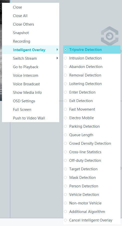
Viewing Backend Alarms on the iClient S100
- View the behavior analysis task status.
- On the iClient S100 home page, choose .
- Right-click a device and choose Task Management.
- Set search criteria. You can click Advanced and set advanced search criteria.
After the setting, click Search. Then, you can view the behavior analysis task progress and status in the task list.
- View behavior analysis alarms on the Video Alarm page.
For details about how to view the latest or historical alarms, see Viewing Alarms (on the iClient S100).
Area Entry Detection
Feature Description
Definition
The system generates an alarm when an object is detected entering a specified area.
- Allows users to specify multiple polygonal detection areas.
- Detects and distinguishes multiple objects that enter a specified area, and generates alarms.
- Displays alarm information including the alarm type, occurrence time, duration, and object labeling.
Customer Benefits
The system automatically detects key information in video feeds through intelligent analysis, reducing labor costs and improving detection efficiency. Different intelligent analysis functions apply to different scenarios.
Application Scenario
This feature is used to detect objects that enter a key protection area.
Requirements
NE |
Version Requirement |
License Requirement |
Function |
|---|---|---|---|
HWT-IVS1800-D/HWT-IVS1800-E |
11.1.0 and later versions |
N/A |
Handles area entry alarms. |
SDC |
Common perimeter detection: 8.0.0 and later versions (configurable on the LDU only in 8.2.0 and later versions) Enhanced perimeter detection: 9.0.0 and later versions |
N/A |
Supports behavior analysis (perimeter detection). Enhanced perimeter detection is recommended. |
Application Limitations
- Onsite conditions such as illumination and shooting angles affect the detection accuracy.
- Alarms can be triggered concurrently for a maximum of nine objects.
- Currently, this feature is not supported on the iClient S100.
Feature Configuration (Based on Cameras)
Scenario Description
Table 4-156 describes the support for this feature in different client scenarios.
Client |
Feature Support |
Reference |
|---|---|---|
LDU |
Supported |
For details, see Procedure (on the LDU). |
Camera web system |
Supported |
Complete the configuration by referring to the product documentation of cameras. |
iClient S100 |
Supported |
For details, see Procedure (on the iClient S100). |
Prerequisites
- You have connected a camera that supports intelligent analysis.
- You have set the parameters listed in Setting Global Parameters (Configuring Frontend Behavior Analysis on the LDU) on the LDU.
- You have enabled behavior analysis for the camera and set global parameters on the iClient S100. For details, see Setting Global Parameters (Configuring Frontend Behavior Analysis on the iClient S100).
- Alarm linkage has been configured on the iClient S100. For details, see Configuring Alarm Linkage.
Procedure (on the LDU)
To view the configuration guide video, you can click in the upper left corner on the Configuration tab page, and scan the QR code.
- Log in to the LDU as the admin user. ( Logging In to the LDU)
- Click
 in the upper left corner.
 - Choose .
- Configure area entry detection, as shown in Figure 4-174.
Table 4-157 describes the key parameters and buttons.
Table 4-157 Parameter/Button descriptionType
Parameter/Button
Description
Detection Area
Detection Object
Type of objects that can be detected.
- Pedestrian
- Motor vehicle
- Non-motorized vehicle
No.
ID of a detection area. A maximum of four detection areas can be drawn.
Operation
Column containing the icons for drawing or deleting a detection area on the live video image.
Switch
Button for enabling or disabling a detection area.
Sound And Light Alarm
NOTE:The configurations of this function cannot be applied to other devices.
Audio switch/Twinkle switch
Indicates whether to produce audible alarms (playing audio files) or visual alarms (blinking light) when an alarm is triggered.
Audio Output
Audio file to be played when an alarm is triggered.
- You can directly use this function when an intelligent IR/white-light camera with intercom is used.
- To use this function when a camera other than the intelligent IR/white-light camera with intercom is used, you need to set audio parameters for the camera and connect the camera to an external audio output device.
Frequency
Number of times for playing an audio file when an alarm is triggered.
Twinkle Freq
Frequency at which the light blinks when an alarm is triggered. You can set this parameter to Low frequency, Medium frequency, or High frequency as required.
Currently, the visual alarm (blinking light) function is available only for intelligent IR/white-light cameras with intercom. You need to set light-related parameters.
Twinkle Time(s)
Period in which the light blinks when an alarm is triggered.
Alarm Settings
Alarm Sensitivity
Detection sensitivity of the system.
The value ranges from 1 to 100. A larger value indicates higher sensitivity.
Alarm Interval (s)
Interval at which alarms are checked, in seconds.
Pre-determined Alarm Position
Part of an object based on which detection is performed.
- Center: An object can be detected only when its central part enters the detection area.
- Top: An object can be detected only when its top part enters the detection area.
- Bottom: An object can be detected only when its bottom part enters the detection area.
The criteria for determining whether an object enters the detection area are related to Pre-determined Alarm Position. For example, if Pre-determined Alarm Position is set to Center, an alarm is triggered when the central part of an object enters the detection area.
- Configure an alert plan, as shown in Figure 4-175.
Table 4-158 describes the key parameters and buttons.
Table 4-158 Parameter/Button descriptionParameter/Button
Description
Add
Button for adding an alert plan. A maximum of eight alert plans are supported.
Delete All
Button for deleting all alert plans.
Button for enabling or disabling an alert plan. If you toggle on Status, the alert plan takes effect.
Day
Date on which an alert plan is executed.
The default value is Every Day.
Mode
Mode in which an alert plan is executed.
- Weekly
- One-off
- Configure an alarm linkage policy, as shown in Figure 4-176.
Table 4-159 describes the key parameters.
Table 4-159 Parameter descriptionType
Parameter
Description
Common Linkage
Display ID
Indicates whether to display the status icon of the camera that triggers an alarm on the live video viewing page. This function is used to notify users of an alarm generated by the current camera.
Full-Screen Alarm
Indicates whether to display alarms in full screen mode.
After this function is enabled, if a camera triggers an alarm and the live video viewing page is displayed on the LDU, the live video of the camera is played in full screen mode for 5s.
CAUTION:If another alarm is generated when live video is being played in full screen mode, this function is not triggered.
Send Email
- Indicates whether to send email notifications. After this function is enabled, the system sends an email to the configured email recipient when a service alarm is generated.
- You can click to customize the alarm email recipient and email body.
The email address for sending service alarms needs to be customized on the OMU portal.
For details about how to set the email address for sending service alarms, see How Do I Configure Connection to the SMTP Server?.
Recording
Channel
Camera to be linked to record video when an alarm is triggered.
Duration(s)
Customized recording duration. The value ranges from 5 to 3600, in seconds. You are advised to set this parameter to a value greater than or equal to 60 (default).
Triggered Snapshot
Channel
Camera to be linked to take snapshots when an alarm is triggered.
NOTE:If both snapshot taking and email sending are configured for alarm linkage, you can obtain both the alarm-triggered snapshots and the snapshots sent in the email.
Stop Recording
Channel
Camera to be linked to stop video recording when an alarm is triggered.
I/O Alarm
Channel ID
Alarm reporting channel.
Duration(s)
Customized alarm linkage duration.
The value ranges from 1 to 3600, in seconds.
NOTE:If the specified alarm linkage duration is different from the I/O alarm output duration configured in How Do I Connect Cables and Configure Alarm Input and Output Ports?, the shorter alarm duration is used.
For example, if the I/O alarm output duration is set to 20s and the alarm linkage duration is set to 30s, the actual alarm output duration is 20s.
Invoke Preset Position
Channel
Camera to be linked. When a service alarm is generated, the linked camera rotates to the specified preset position.
Before enabling preset position linkage, ensure that a preset position has been configured for the camera to be linked. For details about how to configure a preset position, see Feature Configuration.
Device
Name of the camera that is linked to a preset position.
Position
Preset position linked to the camera.

Procedure (on the iClient S100)
- On the iClient S100 home page, choose Maintenance Management > Smart Configuration.
- Select a camera for which you want to configure a behavior analysis policy.
- Choose and set related parameters.
- Set parameters in the Parameter Settings area. Table 4-160 describes the parameters.
Table 4-160 Parameter description
Parameter
Description
Detection Target
Type of objects that can be detected. (This parameter is not involved when the behavior analysis type is abandoned object detection, removed object detection, or electric bike detection.)
- Pedestrian
- Motor vehicle
- Non-motorized vehicle
Alarm Detection Interval(s)
Interval at which the system checks for new alarms, in seconds. If any alarm is detected, the system reports the alarm to the iClient S100.
NOTE:To prevent a flood of alarms, the system reports only one alarm even if it detects multiple alarms within the specified interval.
Target Recognition Mode
Part of an object based on which detection is performed.
- centered: An object can be detected only when its central part enters the detection area.
- Bottom: An object can be detected only when its bottom part enters the detection area.
- tops: An object can be detected only when its top part enters the detection area.
Sensitivity
Detection sensitivity.
The value ranges from 1 to 100. A larger value indicates higher sensitivity.
- Set audible and visual alarm parameters. Table 4-161 describes the parameters.
Table 4-161 Audible and visual alarm parameters
Parameter
Description
Requirement on the Camera
Enable audio alarms
Indicates whether to produce audible alarms (play audio files) when an alarm is triggered.
- You can directly use this function when an intelligent IR/white-light camera with intercom is used.
- To use this function when a camera other than the intelligent IR/white-light camera with intercom is used, you need to set audio parameters for the camera and connect the camera to an external audio output device.
Audio file
Audio file to be played when an alarm is triggered.
To import an audio file to the iClient S100, choose Maintenance Management > Video Device > Device List on the home page, double-click the required camera that is connected to a device, and add an audio file on the Audio Channel tab page.
Playback times
Number of times for playing an audio file when an alarm is triggered.
Enable light flashing alarm
Indicates whether to produce visual alarms (blinking lights) when an alarm is triggered.
Currently, these functions are available when an intelligent IR/white-light camera with intercom is used. You need to set light-related parameters.
White light illuminator
Frequency at which the light blinks when an alarm is triggered. You can set this parameter to Low, Middle, High, or Steady on as required.
Flash duration (s)
Period in which the light blinks when an alarm is triggered.
- Set area parameters, as shown in Figure 4-177. Table 4-162 describes the parameters and buttons.
Table 4-162 Area settings
Parameter
Description
Area
Button for adding a detection area. A maximum of four detection areas can be configured for analyzing a type of behavior. A maximum of 10 detection areas can be configured for analyzing all types of behavior.
You can select and drag the detection area or change its shape and size.
Delete
Button for deleting a selected detection area.
Status
- If the parameter is toggled on, the frame of a detection area turns red and the detection takes effect.
- If the parameter is toggled off, the frame of a detection area turns white and the detection stops.
- Set plan parameters. Table 4-163 describes the parameters.
When the iClient S100 and an HWT-IVS1800 are in different time zones, the time set in the Plan Settings area refers to the time of the HWT-IVS1800.
Table 4-163 Plan settingsParameter/Button
Description
Add
Button for adding an alert plan. A maximum of eight alert plans are supported.
All Delete
Button for deleting all alert plans.
Start Time/End Time
Time segment during which alert is to be deployed.
Date
Date on which an alert plan is to be executed.
- Every day
- Monday to Sunday
Mode
Indicates whether to cyclically execute an alert plan.
- Weekly
- One-off
Operation
To delete the current alert plan, click
in the Operation column.
- Set parameters in the Parameter Settings area. Table 4-160 describes the parameters.
- Click Save.

Feature Configuration (Based on the HWT-IVS1800)
This feature applies only to PoC scenarios outside the Chinese mainland.
Scenario Description
- Table 4-164 describes the support for this feature in different client scenarios.
Client |
Feature Support |
Reference |
|---|---|---|
LDU |
Supported |
For details, see Procedure (on the LDU). |
iClient S100 |
Supported |
For details, see Procedure (on the iClient S100). |
- After local intelligence is enabled or an analysis task is created for a camera, do not modify the attributes of the camera. Otherwise, target recognition and video structuring tasks will become invalid, and you will need to delete and recreate the tasks.
Prerequisites
You have set the parameters listed in Public Configurations.
Procedure (on the LDU)
To view the configuration guide video, you can click in the upper left corner on the Configuration tab page, and scan the QR code.
- Log in to the LDU as the admin user. ( Logging In to the LDU)
- Right-click on the desktop and choose Intelligent Application.
- Choose Local Device Intelligence > Behavior Analysis > Area Entry.
- Set basic parameters of area entry detection, as shown in Figure 4-178.
Table 4-165 describes the parameters.
Table 4-165 Parameter descriptionParameter
Description
Button for enabling or disabling intrusion detection.
Detection Object
Type of objects to be detected. The options include Pedestrian and Motor vehicle. After you select a detection object type, the camera automatically reports an intrusion alarm upon detecting an object of the selected type.
No.
ID of a detection area. A maximum of four detection areas can be drawn.
Operation
Column containing the icons for drawing or deleting a detection area on the live video image.
You can draw detection areas based on the following rules:
- You are advised to draw lines clockwise. The lines you draw cannot cross each other or form a sharp acute angle. Otherwise, detection areas may fail to be drawn.
- Do not draw polygonal areas that overlap with each other. Otherwise, false negatives may occur.
Min Target
Minimum resolution of an object that can be detected, in pixels.
Max Target
Maximum resolution of a target that can be detected, in pixels.
Pre-determined Alarm Position
- Center: An object can be detected only when its central part enters the detection area.
- Top: An object can be detected only when its top part enters the detection area.
- Bottom: An object can be detected only when its bottom part enters the detection area.
Target Detection
Sensitivity for the system to trigger alarms when detecting objects in the detection area.
Higher sensitivity indicates a higher probability of triggering alarms and a higher false positive rate. The options are as follows:
- Lowest
- Low
- Lower
- Medium
- High (default)
Max Targets
Maximum number of objects that can be analyzed and processed in a detection area.
Alarm Interval(s)
Interval at which the system checks for new alarms.
To prevent a flood of alarms, the system reports only one alarm even if it detects multiple alarms within the specified interval.
- Configure an alert plan, as shown in Figure 4-179.
Table 4-166 describes the key parameters.
Table 4-166 Parameter descriptionParameter
Description
Add
Button for adding an alert plan.
Delete All
Button for deleting all alert plans.
Status
Indicates whether to enable an alert plan.
Start Time/End Time
Execution duration of the alert plan.
Date
Date on which an alert plan is to be executed.
- Every day
- Monday to Sunday
Mode
Indicates whether to cyclically execute an alert plan.
- Weekly
- One-off
Operation
Column containing the icon for deleting the alert plan.
- (Optional) Configure alarm linkage, as shown in Figure 4-180.
Table 4-167 describes the parameters.
Table 4-167 Parameter descriptionParameter
Description
Severity
Alarm severity. The default value is Minor. You do not need to set this parameter.
Channel
Camera to be linked to record video when an alarm is triggered.
When a camera triggers an alarm, the selected camera starts to record video.
Snapshot channel
Camera to be linked to take snapshots when an alarm is triggered.
When a camera triggers an alarm, the selected camera starts to take snapshots.
NOTE:If both snapshot taking and email sending are configured for alarm linkage, you can obtain both the alarm-triggered snapshot and the snapshot sent in the email.
- Click Apply.

Procedure (on the iClient S100)
- On the iClient S100 home page, choose .
- Right-click a certain HWT-IVS1800 and choose Task Management.
- Click New Task. In the New Task dialog box that is displayed, choose the desired behavior analysis task in the navigation tree on the left, and set related parameters, as shown in Figure 4-181.
Table 4-168 General parameters
Parameter
Description
Indicates whether to enable the current behavior analysis task.
Detection Object
Detection object.
- Pedestrian
- Motor vehicle
Alarm Interval(s)
Interval at which the system checks for new alarms, in seconds.
Dwell (s)
Time during which an object can loiter in the detection area. If an object loiters in the detection area for a period longer than the specified time, an alarm is generated.
This parameter is available only when you choose Loitering in the navigation tree.
The value ranges from 1 to 180 for loitering detection.
Reference
Part of an object based on which the detection is performed.
Target center: An object can be detected only when its central part enters the detection area.
Bottom center: An object can be detected only when its bottom part enters the detection area.
Top center: An object can be detected only when its top part enters the detection area.
For example, if this parameter is set to Top center, an alarm is generated only when the top part of the object is in the detection area.
Minimum detection target
Minimum resolution of an object that can be detected, in pixels.
Maximum detection target
Maximum resolution of an object that can be detected, in pixels.
Detection Area
Button for drawing a detection area. You can double-click the left mouse button to complete drawing.
You can draw detection areas based on the following rules:
- You are advised to draw lines clockwise. The lines you draw cannot cross each other or form a sharp acute angle. Otherwise, detection areas may fail to be drawn.
- Do not draw polygonal areas that overlap with each other. Otherwise, false negatives may occur.
- Click Save.
Feature Verification
Viewing Alarms (on the LDU)
- Log in to the LDU as the admin user. ( Logging In to the LDU)
- View alarms on the LDU.
- Viewing real-time alarms
- Right-click on the desktop and choose Live > Alarm List.
- Click and select the type of alarms to be viewed, as shown in Figure 4-182.
- Click an alarm card in the alarm list to view the alarm in full screen mode, as shown in Figure 4-183.
- By default, the alarm-triggered video is 10s long (5s before and 5s after the alarm time).
- If you click , the alarm list on the left stops refreshing the latest alarms. If you click again, the system refreshes all new alarms generated after the alarm refresh stops.
- Viewing historical alarms
- Right-click on the desktop and choose Retrieval.
- Choose Event Retrieval.
- View alarms, as shown in Figure 4-184.
You can click the Browsing Status icon to switch the alarm browsing mode. Alarms in the alarm center can be browsed in card or list mode.
- Viewing real-time alarms
Viewing Frontend Alarms on the iClient S100
- Viewing real-time intelligent analysis results
- On the iClient S100 home page, choose .
- Double-click an online camera in the Devices area or drag the online camera to a live video pane. Then you can view live video from this camera.
- Right-click a live video pane and choose Intelligent Overlay > Enter Detection, as shown in Figure 4-185. The real-time intelligent analysis result is superimposed on the video image.
- Viewing alarms
For details about how to view the latest or historical alarms, see Viewing Alarms (on the iClient S100).
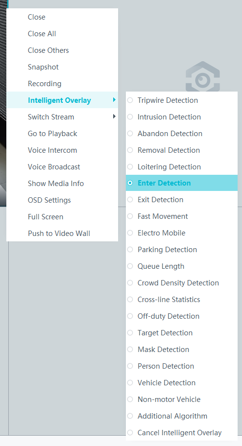
Viewing Backend Alarms on the iClient S100
- View the behavior analysis task status.
- On the iClient S100 home page, choose .
- Right-click a device and choose Task Management.
- Set search criteria. You can click Advanced and set advanced search criteria.
After the setting, click Search. Then, you can view the behavior analysis task progress and status in the task list.
- View behavior analysis alarms on the Video Alarm page.
For details about how to view the latest or historical alarms, see Viewing Alarms (on the iClient S100).
Area Exit Detection
Feature Description
Definition
The system generates an alarm when an object is detected exiting a specified area.
- Allows users to specify multiple polygonal detection areas.
- Detects and distinguishes multiple objects that exit a specified area, and generates alarms.
- Displays alarm information including the alarm type, occurrence time, duration, and object labeling.
Customer Benefits
The system automatically detects key information in video feeds through intelligent analysis, reducing labor costs and improving detection efficiency. Different intelligent analysis functions apply to different scenarios.
Application Scenario
This feature is used to detect objects that exit a key protection area.
Requirements
NE |
Version Requirement |
License Requirement |
Function |
|---|---|---|---|
HWT-IVS1800-D/HWT-IVS1800-E |
11.1.0 and later versions |
N/A |
Handles area exit alarms. |
SDC |
Common perimeter detection: 8.0.0 and later versions (configurable on the LDU only in 8.2.0 and later versions) Enhanced perimeter detection: 9.0.0 and later versions |
N/A |
Supports behavior analysis (perimeter detection). Enhanced perimeter detection is recommended. |
Application Limitations
- Onsite conditions such as illumination and shooting angles affect the detection accuracy.
- Alarms can be triggered concurrently for a maximum of nine objects.
- Currently, this feature is not supported on the iClient S100.
Feature Configuration (Based on Cameras)
Scenario Description
Table 4-169 describes the support for this feature in different client scenarios.
Client |
Feature Support |
Reference |
|---|---|---|
LDU |
Supported |
For details, see Procedure (on the LDU). |
Camera web system |
Supported |
Complete the configuration by referring to the product documentation of cameras. |
iClient S100 |
Supported |
For details, see Procedure (on the iClient S100). |
Prerequisites
- You have connected a camera that supports intelligent analysis.
- You have set the parameters listed in Setting Global Parameters (Configuring Frontend Behavior Analysis on the LDU) on the LDU.
- You have enabled behavior analysis for the camera and set global parameters on the iClient S100. For details, see Setting Global Parameters (Configuring Frontend Behavior Analysis on the iClient S100).
- Alarm linkage has been configured on the iClient S100. For details, see Configuring Alarm Linkage.
Procedure (on the LDU)
To view the configuration guide video, you can click in the upper left corner on the Configuration tab page, and scan the QR code.
- Log in to the LDU as the admin user. ( Logging In to the LDU)
- Click
 in the upper left corner.
 - Choose .
- Configure area exit detection, as shown in Figure 4-186.
Table 4-170 describes the key parameters.
Table 4-170 Parameter/Button descriptionType
Parameter/Button
Description
Detection Area
Detection Object
Type of objects that can be detected.
- Pedestrian
- Motor vehicle
- Non-motorized vehicle
No.
ID of a detection area. A maximum of four detection areas can be drawn.
Operation
Column containing the icons for drawing or deleting a detection area on the live video image.
Switch
Button for enabling or disabling a detection area.
Sound And Light Alarm
NOTE:The configurations of this function cannot be applied to other devices.
Audio switch/Twinkle switch
Indicates whether to produce audible alarms (playing audio files) or visual alarms (blinking light) when an alarm is triggered.
Audio Output
Audio file to be played when an alarm is triggered.
- You can directly use this function when an intelligent IR/white-light camera with intercom is used.
- To use this function when a camera other than the intelligent IR/white-light camera with intercom is used, you need to set audio parameters for the camera and connect the camera to an external audio output device.
Frequency
Number of times for playing an audio file when an alarm is triggered.
Twinkle Freq
Frequency at which the light blinks when an alarm is triggered. You can set this parameter to Low frequency, Medium frequency, or High frequency as required.
Currently, the visual alarm (blinking light) function is available only for intelligent IR/white-light cameras with intercom. You need to set light-related parameters.
Twinkle Time(s)
Period in which the light blinks when an alarm is triggered.
Alarm Settings
Alarm Sensitivity
Detection sensitivity of the system.
The value ranges from 1 to 100. A larger value indicates higher sensitivity.
Alarm Interval (s)
Interval at which alarms are checked, in seconds.
Pre-determined Alarm Position
Part of an object based on which detection is performed.
- Center: An object can be detected only when its central part enters the detection area.
- Top: An object can be detected only when its top part enters the detection area.
- Bottom: An object can be detected only when its bottom part enters the detection area.
The criteria for determining whether an object enters the detection area are related to Pre-determined Alarm Position. For example, if Pre-determined Alarm Position is set to Center, an alarm is triggered when the central part of an object enters the detection area.
- Configure an alert plan, as shown in Figure 4-187.
Table 4-171 describes the key parameters.
Table 4-171 Parameter/Button descriptionParameter/Button
Description
Add
Button for adding an alert plan. A maximum of eight alert plans are supported.
Delete All
Button for deleting all alert plans.
Button for enabling or disabling an alert plan. If you toggle on Status, the alert plan takes effect.
Day
Date on which an alert plan is executed.
The default value is Every Day.
Mode
Mode in which an alert plan is executed.
- Weekly
- One-off
- Configure an alarm linkage policy, as shown in Figure 4-188.
Table 4-172 describes the key parameters.
Table 4-172 Parameter descriptionType
Parameter
Description
Common Linkage
Display ID
Indicates whether to display the status icon of the camera that triggers an alarm on the live video viewing page. This function is used to notify users of an alarm generated by the current camera.
Full-Screen Alarm
Indicates whether to display alarms in full screen mode.
After this function is enabled, if a camera triggers an alarm and the live video viewing page is displayed on the LDU, the live video of the camera is played in full screen mode for 5s.
CAUTION:If another alarm is generated when live video is being played in full screen mode, this function is not triggered.
Send Email
- Indicates whether to send email notifications. After this function is enabled, the system sends an email to the configured email recipient when a service alarm is generated.
- You can click to customize the alarm email recipient and email body.
The email address for sending service alarms needs to be customized on the OMU portal.
For details about how to set the email address for sending service alarms, see How Do I Configure Connection to the SMTP Server?.
Recording
Channel
Camera to be linked to record video when an alarm is triggered.
Duration(s)
Customized recording duration. The value ranges from 5 to 3600, in seconds. You are advised to set this parameter to a value greater than or equal to 60 (default).
Triggered Snapshot
Channel
Camera to be linked to take snapshots when an alarm is triggered.
NOTE:If both snapshot taking and email sending are configured for alarm linkage, you can obtain both the alarm-triggered snapshots and the snapshots sent in the email.
Stop Recording
Channel
Camera to be linked to stop video recording when an alarm is triggered.
I/O Alarm
Channel ID
Alarm reporting channel.
Duration(s)
Customized alarm linkage duration.
The value ranges from 1 to 3600, in seconds.
NOTE:If the specified alarm linkage duration is different from the I/O alarm output duration configured in How Do I Connect Cables and Configure Alarm Input and Output Ports?, the shorter alarm duration is used.
For example, if the I/O alarm output duration is set to 20s and the alarm linkage duration is set to 30s, the actual alarm output duration is 20s.
Invoke Preset Position
Channel
Camera to be linked. When a service alarm is generated, the linked camera rotates to the specified preset position.
Before enabling preset position linkage, ensure that a preset position has been configured for the camera to be linked. For details about how to configure a preset position, see Feature Configuration.
Device
Name of the camera that is linked to a preset position.
Position
Preset position linked to the camera.

Procedure (on the iClient S100)
- On the iClient S100 home page, choose Maintenance Management > Smart Configuration.
- Select a camera for which you want to configure a behavior analysis policy.
- Click the Behavior Analysis tab and then the Area Exit tab, and set related parameters.
- Set parameters in the Parameter Settings area. Table 4-173 describes the parameters.
Table 4-173 Parameter description
Parameter
Description
Detection Target
Type of objects that can be detected. (This parameter is not involved when the behavior analysis type is abandoned object detection, removed object detection, or electric bike detection.)
- Pedestrian
- Motor vehicle
- Non-motorized vehicle
Alarm Detection Interval(s)
Interval at which the system checks for new alarms, in seconds. If any alarm is detected, the system reports the alarm to the iClient S100.
NOTE:To prevent a flood of alarms, the system reports only one alarm even if it detects multiple alarms within the specified interval.
Target Recognition Mode
Part of an object based on which detection is performed.
- centered: An object can be detected only when its central part enters the detection area.
- Bottom: An object can be detected only when its bottom part enters the detection area.
- tops: An object can be detected only when its top part enters the detection area.
Sensitivity
Detection sensitivity.
The value ranges from 1 to 100. A larger value indicates higher sensitivity.
- Set audible and visual alarm parameters. Table 4-174 describes the parameters.
Table 4-174 Audible and visual alarm parameters
Parameter
Description
Requirement on the Camera
Enable audio alarms
Indicates whether to produce audible alarms (play audio files) when an alarm is triggered.
- You can directly use this function when an intelligent IR/white-light camera with intercom is used.
- To use this function when a camera other than the intelligent IR/white-light camera with intercom is used, you need to set audio parameters for the camera and connect the camera to an external audio output device.
Audio file
Audio file to be played when an alarm is triggered.
To import an audio file to the iClient S100, choose Maintenance Management > Video Device > Device List on the home page, double-click the required camera that is connected to a device, and add an audio file on the Audio Channel tab page.
Playback times
Number of times for playing an audio file when an alarm is triggered.
Enable light flashing alarm
Indicates whether to produce visual alarms (blinking lights) when an alarm is triggered.
Currently, these functions are available when an intelligent IR/white-light camera with intercom is used. You need to set light-related parameters.
White light illuminator
Frequency at which the light blinks when an alarm is triggered. You can set this parameter to Low, Middle, High, or Steady on as required.
Flash duration (s)
Period in which the light blinks when an alarm is triggered.
- Set area parameters, as shown in Figure 4-189. Table 4-175 describes the parameters and buttons.
Table 4-175 Area settings
Parameter/Button
Description
Area
Button for adding a detection area. A maximum of four detection areas can be configured for analyzing a type of behavior. A maximum of 10 detection areas can be configured for analyzing all types of behavior.
You can select and drag the detection area or change its shape and size.
Delete
Button for deleting a selected detection area.
Status
- If the parameter is toggled on, the frame of a detection area turns red and the detection takes effect.
- If the parameter is toggled off, the frame of a detection area turns white and the detection stops.
- Set plan parameters. Table 4-176 describes the parameters.
When the iClient S100 and an HWT-IVS1800 are in different time zones, the time set in the Plan Settings area refers to the time of the HWT-IVS1800.
Table 4-176 Plan settingsParameter/Button
Description
Add
Button for adding an alert plan. A maximum of eight alert plans are supported.
All Delete
Button for deleting all alert plans.
Start Time/End Time
Time segment during which alert is to be deployed.
Date
Date on which an alert plan is to be executed.
- Every day
- Monday to Sunday
Mode
Indicates whether to cyclically execute an alert plan.
- Weekly
- One-off
Operation
To delete the current alert plan, click
in the Operation column.
- Set parameters in the Parameter Settings area. Table 4-173 describes the parameters.
- Click Save.

Feature Configuration (Based on the HWT-IVS1800)
This feature applies only to PoC scenarios outside the Chinese mainland.
Scenario Description
- Table 4-177 describes the support for this feature in different client scenarios.
Client |
Feature Support |
Reference |
|---|---|---|
LDU |
Supported |
For details, see Procedure (on the LDU). |
iClient S100 |
Supported |
For details, see Procedure (on the iClient S100). |
- After local intelligence is enabled or an analysis task is created for a camera, do not modify the attributes of the camera. Otherwise, target recognition and video structuring tasks will become invalid, and you will need to delete and recreate the tasks.
Prerequisites
You have set the parameters listed in Public Configurations.
Procedure (on the LDU)
To view the configuration guide video, you can click in the upper left corner on the Configuration tab page, and scan the QR code.
- Log in to the LDU as the admin user. ( Logging In to the LDU)
- Right-click on the desktop and choose Intelligent Application.
- Choose Local Device Intelligence > Behavior Analysis > Area Exit.
- Set basic parameters of area exit detection, as shown in Figure 4-190.
Table 4-178 describes the parameters.
Table 4-178 Parameter descriptionParameter
Description
Button for enabling or disabling intrusion detection.
Detection Object
Type of objects to be detected. The options include Pedestrian and Motor vehicle. After you select a detection object type, the camera automatically reports an intrusion alarm upon detecting an object of the selected type.
No.
ID of a detection area. A maximum of four detection areas can be drawn.
Operation
Column containing the icons for drawing or deleting a detection area on the live video image.
You can draw detection areas based on the following rules:
- You are advised to draw lines clockwise. The lines you draw cannot cross each other or form a sharp acute angle. Otherwise, detection areas may fail to be drawn.
- Do not draw polygonal areas that overlap with each other. Otherwise, false negatives may occur.
Min Target
Minimum resolution of an object that can be detected, in pixels.
Max Target
Maximum resolution of a target that can be detected, in pixels.
Pre-determined Alarm Position
- Center: An object can be detected only when its central part enters the detection area.
- Top: An object can be detected only when its top part enters the detection area.
- Bottom: An object can be detected only when its bottom part enters the detection area.
Target Detection
Sensitivity for the system to trigger alarms when detecting objects in the detection area.
Higher sensitivity indicates a higher probability of triggering alarms and a higher false positive rate. The options are as follows:
- Lowest
- Low
- Lower
- Medium
- High (default)
Max Targets
Maximum number of objects that can be analyzed and processed in a detection area.
Alarm Interval(s)
Interval at which the system checks for new alarms.
To prevent a flood of alarms, the system reports only one alarm even if it detects multiple alarms within the specified interval.
- Configure an alert plan, as shown in Figure 4-191.
Table 4-179 describes the key parameters.
Table 4-179 Parameter descriptionParameter
Description
Add
Button for adding an alert plan.
Delete All
Button for deleting all alert plans.
Status
Indicates whether to enable an alert plan.
Start Time/End Time
Execution duration of the alert plan.
Date
Date on which an alert plan is to be executed.
- Every day
- Monday to Sunday
Mode
Indicates whether to cyclically execute an alert plan.
- Weekly
- One-off
Operation
Column containing the icon for deleting the alert plan.
- (Optional) Configure alarm linkage, as shown in Figure 4-192.
Table 4-180 describes the parameters.
Table 4-180 Parameter descriptionParameter
Description
Severity
Alarm severity. The default value is Minor. You do not need to set this parameter.
Channel
Camera to be linked to record video when an alarm is triggered.
When a camera triggers an alarm, the selected camera starts to record video.
Snapshot channel
Camera to be linked to take snapshots when an alarm is triggered.
When a camera triggers an alarm, the selected camera starts to take snapshots.
NOTE:If both snapshot taking and email sending are configured for alarm linkage, you can obtain both the alarm-triggered snapshot and the snapshot sent in the email.
- Click Apply.

Procedure (on the iClient S100)
- On the iClient S100 home page, choose .
- Right-click an HWT-IVS1800 and choose Task Management from the shortcut menu.
- Click New Task. In the New Task dialog box that is displayed, choose the desired behavior analysis task in the navigation tree on the left, and set related parameters, as shown in Figure 4-193.
Table 4-181 General parameters
Parameter
Description
Indicates whether to enable the current behavior analysis task.
Detection Object
Detection object.
- Pedestrian
- Motor vehicle
Alarm Interval(s)
Interval at which the system checks for new alarms, in seconds.
Dwell (s)
Time during which an object can loiter in the detection area. If an object loiters in the detection area for a period longer than the specified time, an alarm is generated.
This parameter is available only when you choose Loitering in the navigation tree.
The value ranges from 1 to 180 for loitering detection.
Reference
Part of an object based on which the detection is performed.
Target center: An object can be detected only when its central part enters the detection area.
Bottom center: An object can be detected only when its bottom part enters the detection area.
Top center: An object can be detected only when its top part enters the detection area.
For example, if this parameter is set to Top center, an alarm is generated only when the top part of the object is in the detection area.
Minimum detection target
Minimum resolution of an object that can be detected, in pixels.
Maximum detection target
Maximum resolution of an object that can be detected, in pixels.
Detection Area
Button for drawing a detection area. You can double-click the left mouse button to complete drawing.
You can draw detection areas based on the following rules:
- You are advised to draw lines clockwise. The lines you draw cannot cross each other or form a sharp acute angle. Otherwise, detection areas may fail to be drawn.
- Do not draw polygonal areas that overlap with each other. Otherwise, false negatives may occur.
- Click Save.
Feature Verification
Viewing Alarms (on the LDU)
- Log in to the LDU as the admin user. ( Logging In to the LDU)
- View alarms on the LDU.
- Viewing real-time alarms
- Right-click on the desktop and choose Live > Alarm List.
- Click and select the type of alarms to be viewed, as shown in Figure 4-194.
- Click an alarm card in the alarm list to view the alarm in full screen mode, as shown in Figure 4-195.
- By default, the alarm-triggered video is 10s long (5s before and 5s after the alarm time).
- If you click , the alarm list on the left stops refreshing the latest alarms. If you click again, the system refreshes all new alarms generated after the alarm refresh stops.
- Viewing historical alarms
- Right-click on the desktop and choose Retrieval.
- Choose Event Retrieval.
- View alarms, as shown in Figure 4-196.
You can click the Browsing Status icon to switch the alarm browsing mode. Alarms in the alarm center can be browsed in card or list mode.
- Viewing real-time alarms
Viewing Frontend Alarms on the iClient S100
- Viewing real-time intelligent analysis results
- On the iClient S100 home page, choose .
- Double-click an online camera in the Devices area or drag the online camera to a live video pane. Then you can view live video from this camera.
- Right-click a live video pane and choose Intelligent Overlay > Exit Detection, as shown in Figure 4-197. The real-time intelligent analysis result is superimposed on the video image.
- Viewing alarms
For details about how to view the latest or historical alarms, see Viewing Alarms (on the iClient S100).
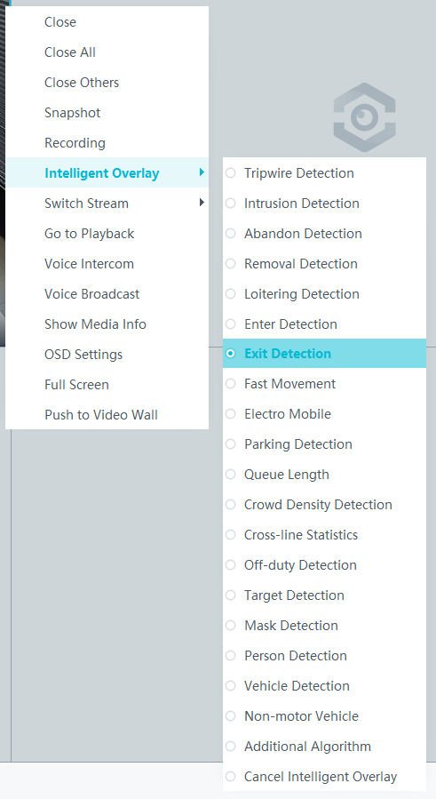
Viewing Backend Alarms on the iClient S100
- View the behavior analysis task status.
- On the iClient S100 home page, choose .
- Right-click a device and choose Task Management.
- Set search criteria. You can click Advanced and set advanced search criteria.
After the setting, click Search. Then, you can view the behavior analysis task progress and status in the task list.
- View behavior analysis alarms on the Video Alarm page.
For details about how to view the latest or historical alarms, see Viewing Alarms (on the iClient S100).
Fast Movement Detection
Feature Description
Definition
An alarm is generated when an object is detected moving fast to prevent security risks from occurrence.
- Allows users to specify multiple polygonal detection areas.
- Detects and distinguishes multiple objects that move fast in a specified area at the same time, and generates alarms.
- Displays alarm information including the alarm type, occurrence time, duration, and object labeling.
Customer Benefits
The system automatically detects key information in video feeds through intelligent analysis, reducing labor costs and improving detection efficiency. Different intelligent analysis functions apply to different scenarios.
Application Scenario
This feature is used to detect objects that move fast to a key protection area.
Requirements
NE |
Version Requirement |
License Requirement |
Function |
|---|---|---|---|
HWT-IVS1800-D/HWT-IVS1800-E |
11.1.0 and later versions |
N/A |
Handles fast movement alarms. |
SDC |
Common perimeter detection: 8.0.0 and later versions (configurable on the LDU only in 8.2.0 and later versions) Enhanced perimeter detection: 9.0.0 and later versions |
N/A |
Supports behavior analysis (perimeter detection). Enhanced perimeter detection is recommended. |
Application Limitations
- Onsite conditions such as illumination and shooting angles affect the detection accuracy.
- Currently, this feature is not supported on the iClient S100.
Feature Configuration (Based on Cameras)
Scenario Description
Table 4-182 describes the support for this feature in different client scenarios.
Client |
Feature Support |
Reference |
|---|---|---|
LDU |
Supported |
For details, see Procedure (on the LDU). |
Camera web system |
Supported |
Complete the configuration by referring to the product documentation of cameras. |
iClient S100 |
Supported |
For details, see Procedure (on the iClient S100). |
Prerequisites
- You have connected a camera that supports intelligent analysis.
- You have set the parameters listed in Setting Global Parameters (Configuring Frontend Behavior Analysis on the LDU) on the LDU.
- You have enabled behavior analysis for the camera and set global parameters on the iClient S100. For details, see Setting Global Parameters (Configuring Frontend Behavior Analysis on the iClient S100).
- Alarm linkage has been configured on the iClient S100. For details, see Configuring Alarm Linkage.
Procedure (on the LDU)
To view the configuration guide video, you can click in the upper left corner on the Configuration tab page, and scan the QR code.
- Log in to the LDU as the admin user. ( Logging In to the LDU)
- Click
 in the upper left corner.
 - Choose .
- Configure fast movement detection, as shown in Figure 4-198.
Table 4-183 describes the key parameters and buttons.
Table 4-183 Parameter/Button descriptionType
Parameter/Button
Description
Detection Area
Detection Object
Type of objects that can be detected.
- Pedestrian
- Motor vehicle
- Non-motorized vehicle
No.
ID of a detection area. A maximum of four detection areas can be drawn.
Operation
Column containing the icons for drawing or deleting a detection area on the live video image.
Switch
Button for enabling or disabling a detection area.
Sound And Light Alarm
NOTE:The configurations of this function cannot be applied to other devices.
Audio switch/Twinkle switch
Indicates whether to produce audible alarms (playing audio files) or visual alarms (blinking light) when an alarm is triggered.
Audio Output
Audio file to be played when an alarm is triggered.
- You can directly use this function when an intelligent IR/white-light camera with intercom is used.
- To use this function when a camera other than the intelligent IR/white-light camera with intercom is used, you need to set audio parameters for the camera and connect the camera to an external audio output device.
Frequency
Number of times for playing an audio file when an alarm is triggered.
Twinkle Freq
Frequency at which the light blinks when an alarm is triggered. You can set this parameter to Low frequency, Medium frequency, or High frequency as required.
Currently, the visual alarm (blinking light) function is available only for intelligent IR/white-light cameras with intercom. You need to set light-related parameters.
Twinkle Time(s)
Period in which the light blinks when an alarm is triggered.
Alarm Settings
Alarm Sensitivity
Detection sensitivity of the system.
The value ranges from 1 to 100. A larger value indicates higher sensitivity.
Alarm Interval (s)
Interval at which alarms are checked, in seconds.
Pre-determined Alarm Position
Part of an object based on which detection is performed.
- Center: An object can be detected only when its central part enters the detection area.
- Top: An object can be detected only when its top part enters the detection area.
- Bottom: An object can be detected only when its bottom part enters the detection area.
The criteria for determining whether an object enters the detection area are related to Pre-determined Alarm Position. For example, if Pre-determined Alarm Position is set to Center, an alarm is triggered when the central part of an object enters the detection area.
- Configure an alert plan, as shown in Figure 4-199.
Table 4-184 describes the key parameters and buttons.
Table 4-184 Parameter/Button descriptionParameter/Button
Description
Add
Button for adding an alert plan. A maximum of eight alert plans are supported.
Delete All
Button for deleting all alert plans.
Button for enabling or disabling an alert plan. If you toggle on Status, the alert plan takes effect.
Day
Date on which an alert plan is executed.
The default value is Every Day.
Mode
Mode in which an alert plan is executed.
- Weekly
- One-off
- Configure an alarm linkage policy, as shown in Figure 4-200.
Table 4-185 describes the key parameters.
Table 4-185 Parameter descriptionType
Parameter
Description
Common Linkage
Display ID
Indicates whether to display the status icon of the camera that triggers an alarm on the live video viewing page. This function is used to notify users of an alarm generated by the current camera.
Full-Screen Alarm
Indicates whether to display alarms in full screen mode.
After this function is enabled, if a camera triggers an alarm and the live video viewing page is displayed on the LDU, the live video of the camera is played in full screen mode for 5s.
CAUTION:If another alarm is generated when live video is being played in full screen mode, this function is not triggered.
Send Email
- Indicates whether to send email notifications. After this function is enabled, the system sends an email to the configured email recipient when a service alarm is generated.
- You can click to customize the alarm email recipient and email body.
The email address for sending service alarms needs to be customized on the OMU portal.
For details about how to set the email address for sending service alarms, see How Do I Configure Connection to the SMTP Server?.
Recording
Channel
Camera to be linked to record video when an alarm is triggered.
Duration(s)
Customized recording duration. The value ranges from 5 to 3600, in seconds. You are advised to set this parameter to a value greater than or equal to 60 (default).
Triggered Snapshot
Channel
Camera to be linked to take snapshots when an alarm is triggered.
NOTE:If both snapshot taking and email sending are configured for alarm linkage, you can obtain both the alarm-triggered snapshots and the snapshots sent in the email.
Stop Recording
Channel
Camera to be linked to stop video recording when an alarm is triggered.
I/O Alarm
Channel ID
Alarm reporting channel.
Duration(s)
Customized alarm linkage duration.
The value ranges from 1 to 3600, in seconds.
NOTE:If the specified alarm linkage duration is different from the I/O alarm output duration configured in How Do I Connect Cables and Configure Alarm Input and Output Ports?, the shorter alarm duration is used.
For example, if the I/O alarm output duration is set to 20s and the alarm linkage duration is set to 30s, the actual alarm output duration is 20s.
Invoke Preset Position
Channel
Camera to be linked. When a service alarm is generated, the linked camera rotates to the specified preset position.
Before enabling preset position linkage, ensure that a preset position has been configured for the camera to be linked. For details about how to configure a preset position, see Feature Configuration.
Device
Name of the camera that is linked to a preset position.
Position
Preset position linked to the camera.

Procedure (on the iClient S100)
- On the iClient S100 home page, choose Maintenance Management > Smart Configuration.
- Select a camera for which you want to configure a behavior analysis policy.
- Click the Behavior Analysis tab and then the Fast Movement Detection tab, and set related parameters.
- Set parameters in the Parameter Settings area. Table 4-186 describes the parameters.
Table 4-186 Parameter description
Parameter
Description
Detection Target
Type of objects that can be detected. (This parameter is not involved when the behavior analysis type is abandoned object detection, removed object detection, or electric bike detection.)
- Pedestrian
- Motor vehicle
- Non-motorized vehicle
Alarm Detection Interval(s)
Interval at which the system checks for new alarms, in seconds. If any alarm is detected, the system reports the alarm to the iClient S100.
NOTE:To prevent a flood of alarms, the system reports only one alarm even if it detects multiple alarms within the specified interval.
Target Recognition Mode
Part of an object based on which detection is performed. Part of an object based on which detection is performed.
- centered: An object can be detected only when its central part enters the detection area.
- Bottom: An object can be detected only when its bottom part enters the detection area.
- tops: An object can be detected only when its top part enters the detection area.
Sensitivity
Detection sensitivity.
The value ranges from 1 to 100. A larger value indicates higher sensitivity.
- Set audible and visual alarm parameters. Table 4-187 describes the parameters.
Table 4-187 Audible and visual alarm parameters
Parameter
Description
Requirement on the Camera
Enable audio alarms
Indicates whether to produce audible alarms (play audio files) when an alarm is triggered.
- You can directly use this function when an intelligent IR/white-light camera with intercom is used.
- To use this function when a camera other than the intelligent IR/white-light camera with intercom is used, you need to set audio parameters for the camera and connect the camera to an external audio output device.
Audio file
Audio file to be played when an alarm is triggered.
To import an audio file to the iClient S100, choose Maintenance Management > Video Device > Device List on the home page, double-click the required camera that is connected to a device, and add an audio file on the Audio Channel tab page.
Playback times
Number of times for playing an audio file when an alarm is triggered.
Enable light flashing alarm
Indicates whether to produce visual alarms (blinking lights) when an alarm is triggered.
Currently, these functions are available when an intelligent IR/white-light camera with intercom is used. You need to set light-related parameters.
White light illuminator
Frequency at which the light blinks when an alarm is triggered. You can set this parameter to Low, Middle, High, or Steady on as required.
Flash duration (s)
Period in which the light blinks when an alarm is triggered.
- Set area parameters, as shown in Figure 4-201. Table 4-188 describes the parameters.
Table 4-188 Area settings
Parameter/Button
Description
Area
Button for adding a detection area. A maximum of four detection areas can be configured for analyzing a type of behavior. A maximum of 10 detection areas can be configured for analyzing all types of behavior.
You can select and drag the detection area or change its shape and size.
Delete
Button for deleting a selected detection area.
Status
- If the parameter is toggled on, the frame of a detection area turns red and the detection takes effect.
- If the parameter is toggled off, the frame of a detection area turns white and the detection stops.
- Set plan parameters. Table 4-189 describes the parameters.
When the iClient S100 and an HWT-IVS1800 are in different time zones, the time set in the Plan Settings area refers to the time of the HWT-IVS1800.
Table 4-189 Plan settingsParameter/Button
Description
Add
Button for adding an alert plan. A maximum of eight alert plans are supported.
All Delete
Button for deleting all alert plans.
Start Time/End Time
Time segment during which alert is to be deployed.
Date
Date on which an alert plan is to be executed.
- Every day
- Monday to Sunday
Mode
Indicates whether to cyclically execute an alert plan.
- Weekly
- One-off
Operation
To delete the current alert plan, click
in the Operation column.
- Set parameters in the Parameter Settings area. Table 4-186 describes the parameters.
- Click Save.

Feature Configuration (Based on the HWT-IVS1800)
This feature applies only to PoC scenarios outside the Chinese mainland.
Scenario Description
- Table 4-190 describes the support for this feature in different client scenarios.
Client |
Feature Support |
Reference |
|---|---|---|
LDU |
Supported |
For details, see Procedure (on the LDU). |
iClient S100 |
Supported |
For details, see Procedure (on the iClient S100). |
- After local intelligence is enabled or an analysis task is created for a camera, do not modify the attributes of the camera. Otherwise, target recognition and video structuring tasks will become invalid, and you will need to delete and recreate the tasks.
Prerequisites
You have set the parameters listed in Public Configurations.
Procedure (on the LDU)
To view the configuration guide video, you can click in the upper left corner on the Configuration tab page, and scan the QR code.
- Log in to the LDU as the admin user. ( Logging In to the LDU)
- Right-click on the desktop and choose Intelligent Application.
- Choose Local Device Intelligence > Behavior Analysis > Fast Movement.
- Set basic parameters of fast movement detection, as shown in Figure 4-202.
Table 4-191 describes the parameters.
Table 4-191 Parameter descriptionParameter
Description
Button for enabling or disabling intrusion detection.
Detection Object
Type of objects to be detected. The options include Pedestrian and Motor vehicle. After you select a detection object type, the camera automatically reports an intrusion alarm upon detecting an object of the selected type.
No.
ID of a detection area. A maximum of four detection areas can be drawn.
Operation
Column containing the icons for drawing or deleting a detection area on the live video image.
You can draw detection areas based on the following rules:
- You are advised to draw lines clockwise. The lines you draw cannot cross each other or form a sharp acute angle. Otherwise, detection areas may fail to be drawn.
- Do not draw polygonal areas that overlap with each other. Otherwise, false negatives may occur.
Min Target
Minimum resolution of an object that can be detected, in pixels.
Max Target
Maximum resolution of a target that can be detected, in pixels.
Pre-determined Alarm Position
- Center: An object can be detected only when its central part enters the detection area.
- Top: An object can be detected only when its top part enters the detection area.
- Bottom: An object can be detected only when its bottom part enters the detection area.
Target Detection
Sensitivity for the system to trigger alarms when detecting objects in the detection area.
Higher sensitivity indicates a higher probability of triggering alarms and a higher false positive rate. The options are as follows:
- Lowest
- Low
- Lower
- Medium
- High (default)
Max Targets
Maximum number of objects that can be analyzed and processed in a detection area.
Alarm Interval(s)
Interval at which the system checks for new alarms.
To prevent a flood of alarms, the system reports only one alarm even if it detects multiple alarms within the specified interval.
- Configure an alert plan, as shown in Figure 4-203.
Table 4-192 describes the key parameters.
Table 4-192 Parameter descriptionParameter
Description
Add
Button for adding an alert plan.
Delete All
Button for deleting all alert plans.
Status
Indicates whether to enable an alert plan.
Start Time/End Time
Execution duration of the alert plan.
Date
Date on which an alert plan is to be executed.
- Every day
- Monday to Sunday
Mode
Indicates whether to cyclically execute an alert plan.
- Weekly
- One-off
Operation
Column containing the icon for deleting the alert plan.
- (Optional) Configure alarm linkage, as shown in Figure 4-204.
Table 4-193 describes the parameters.
Table 4-193 Parameter descriptionParameter
Description
Severity
Alarm severity. The default value is Minor. You do not need to set this parameter.
Channel
Camera to be linked to record video when an alarm is triggered.
When a camera triggers an alarm, the selected camera starts to record video.
Snapshot channel
Camera to be linked to take snapshots when an alarm is triggered.
When a camera triggers an alarm, the selected camera starts to take snapshots.
NOTE:If both snapshot taking and email sending are configured for alarm linkage, you can obtain both the alarm-triggered snapshot and the snapshot sent in the email.
- Click Apply.

Procedure (on the iClient S100)
- On the iClient S100 home page, choose .
- Right-click a certain HWT-IVS1800 and choose Task Management.
- Click New Task. In the New Task dialog box that is displayed, choose the desired behavior analysis task in the navigation tree on the left, and set related parameters, as shown in Figure 4-205.
Table 4-194 General parameters
Parameter
Description
Indicates whether to enable the current behavior analysis task.
Detection Object
Detection object.
- Pedestrian
- Motor vehicle
Alarm Interval(s)
Interval at which the system checks for new alarms, in seconds.
Dwell (s)
Time during which an object can loiter in the detection area. If an object loiters in the detection area for a period longer than the specified time, an alarm is generated.
This parameter is available only when you choose Loitering in the navigation tree.
The value ranges from 1 to 180 for loitering detection.
Reference
Part of an object based on which the detection is performed.
Target center: An object can be detected only when its central part enters the detection area.
Bottom center: An object can be detected only when its bottom part enters the detection area.
Top center: An object can be detected only when its top part enters the detection area.
For example, if this parameter is set to Top center, an alarm is generated only when the top part of the object is in the detection area.
Minimum detection target
Minimum resolution of an object that can be detected, in pixels.
Maximum detection target
Maximum resolution of an object that can be detected, in pixels.
Detection Area
Button for drawing a detection area. You can double-click the left mouse button to complete drawing.
You can draw detection areas based on the following rules:
- You are advised to draw lines clockwise. The lines you draw cannot cross each other or form a sharp acute angle. Otherwise, detection areas may fail to be drawn.
- Do not draw polygonal areas that overlap with each other. Otherwise, false negatives may occur.
- Click Save.
Feature Verification
Viewing Alarms (on the LDU)
- Log in to the LDU as the admin user. ( Logging In to the LDU)
- View alarms on the LDU.
- Viewing real-time alarms
- Right-click on the desktop and choose Live > Alarm List.
- Click and select the type of alarms to be viewed, as shown in Figure 4-206.
- Click an alarm card in the alarm list to view the alarm in full screen mode, as shown in Figure 4-207.
- By default, the alarm-triggered video is 10s long (5s before and 5s after the alarm time).
- If you click , the alarm list on the left stops refreshing the latest alarms. If you click again, the system refreshes all new alarms generated after the alarm refresh stops.
- Viewing historical alarms
- Right-click on the desktop and choose Retrieval.
- Choose Event Retrieval.
- View alarms, as shown in Figure 4-208.
You can click the Browsing Status icon to switch the alarm browsing mode. Alarms in the alarm center can be browsed in card or list mode.
- Viewing real-time alarms
Viewing Frontend Alarms on the iClient S100
- Viewing real-time intelligent analysis results
- On the iClient S100 home page, choose .
- Double-click an online camera in the Devices area or drag the online camera to a live video pane. Then you can view live video from this camera.
- Right-click a live video pane and choose Intelligent Overlay > Fast Movement, as shown in Figure 4-209. The real-time intelligent analysis result is superimposed on the video image.
- Viewing alarms
For details about how to view the latest or historical alarms, see Viewing Alarms (on the iClient S100).
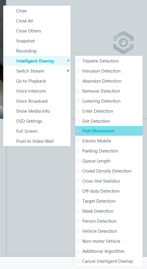
Viewing Backend Alarms on the iClient S100
- View the behavior analysis task status.
- On the iClient S100 home page, choose .
- Right-click a device and choose Task Management.
- Set search criteria. You can click Advanced and set advanced search criteria.
After the setting, click Search. Then, you can view the behavior analysis task progress and status in the task list.
- View behavior analysis alarms on the Video Alarm page.
For details about how to view the latest or historical alarms, see Viewing Alarms (on the iClient S100).
Electric Bike Detection
Feature Description
Definition
The system automatically generates an alarm upon detecting an electric bike in specific areas such as elevators and corridors. This feature provides the following functions:
- Supports multiple detection areas.
- Displays alarm information including the alarm type, occurrence time, duration, and object labeling.
Customer Benefits
Intelligent analysis can be used to automatically detect electric bikes in restricted areas, reducing labor costs and improving efficiency. Applicable intelligent analysis functions vary depending on application scenarios.
Application Scenario
Electric bike detection can be applied in areas where electric bikes are restricted from entry.
Requirements
Involved NE |
Version Requirement |
License Requirement |
Function |
|---|---|---|---|
HWT-IVS1800 |
11.1.0 and later versions |
N/A |
Handles electric bike alarms. |
iClient S100 |
V2.0.0 and later versions |
N/A |
Allows users to configure behavior analysis and alarm display in the camera web system. |
SDC |
9.0.0-LG0001 and later versions |
N/A |
Detects electric bikes. |
Feature Configuration (Based on Cameras)
Prerequisites
- You have enabled behavior analysis for the camera and set global parameters on the iClient S100. For details, see Setting Global Parameters (Configuring Frontend Behavior Analysis on the iClient S100).
- You have set the parameters listed in Setting Global Parameters (Configuring Frontend Behavior Analysis on the LDU) on the LDU.
Procedure (on the LDU)
To view the configuration guide video, you can click in the upper left corner on the Configuration tab page, and scan the QR code.
- Log in to the LDU as the admin user. ( Logging In to the LDU)
- Click
 in the upper left corner.
 - Choose .
- Configure electric bike detection, as shown in Figure 4-210.
Table 4-195 describes the parameters.
Table 4-195 Parameter descriptionType
Parameter
Description
-

Button for enabling or disabling electric bike detection.
Detection Area
No.
ID of a detection area. A maximum of four detection areas can be drawn.
Operation
Column containing the icons for drawing or deleting a detection area on the live video image.
To draw a detection area, select polygon vertices on the video image and right-click the image. The system automatically connects the selected vertices to form a closed area.
Configuration
Alarm Sensitivity
Sensitivity for the system to detect electric bikes entering the detection area.
The value ranges from 1 to 100. A larger value indicates higher sensitivity.
Send only the first alarm of a single target
Indicates whether to send only one alarm when an object enters the detection area.
Alarm sending panorama
Indicates whether to send the captured full image to the video security platform.
Panorama Stacking Target Box
Indicates whether to superimpose a frame on the detected object.
Minimum detection target
Minimum resolution of an object that can be detected, in pixels.
The value ranges from 150 to 1000.
Maximum detection target
Maximum resolution of an object that can be detected, in pixels.
The value ranges from 150 to 1000.
False positive reduction sensitivity
A larger value indicates a lower false positive rate.
The value ranges from 1 to 100.
Sound And Light Alarm
NOTE:The configurations of this function cannot be applied to other devices.
Audio switch/Twinkle switch
Indicates whether to produce audible alarms (playing audio files) or visual alarms (blinking light) when an alarm is triggered.
Audio Output
Audio file to be played when an alarm is triggered.
- You can directly use this function when an intelligent IR/white-light camera with intercom is used.
- To use this function when a camera other than the intelligent IR/white-light camera with intercom is used, you need to set audio parameters for the camera and connect the camera to an external audio output device.
Frequency
Number of times for playing an audio file when an alarm is triggered.
Twinkle Freq
Frequency at which the light blinks when an alarm is triggered. You can set this parameter to Low frequency, Medium frequency, or High frequency as required.
Currently, the visual alarm (blinking light) function is available only for intelligent IR/white-light cameras with intercom. You need to set light-related parameters.
Twinkle Time(s)
Period in which the light blinks when an alarm is triggered.
- Configure an alert plan, as shown in Figure 4-211.
Table 4-196 describes the key parameters and buttons.
Table 4-196 Parameter/Button descriptionParameter/Button
Description
Add
Button for adding an alert plan. A maximum of eight alert plans are supported.
Delete All
Button for deleting all alert plans.
Button for enabling or disabling an alert plan. If you toggle on Status, the alert plan takes effect.
Day
Date on which an alert plan is executed.
The default value is Every Day.
Mode
Mode in which an alert plan is executed.
- Weekly
- One-off
- Configure an alarm linkage policy, as shown in Figure 4-212.
Table 4-197 describes the key parameters.
Table 4-197 Parameter descriptionType
Parameter
Description
Common Linkage
Display ID
Indicates whether to display the status icon of the camera that triggers an alarm on the live video viewing page. This function is used to notify users of an alarm generated by the current camera.
Full-Screen Alarm
Indicates whether to display alarms in full screen mode.
After this function is enabled, if a camera triggers an alarm and the live video viewing page is displayed on the LDU, the live video of the camera is played in full screen mode for 5s.
CAUTION:If another alarm is generated when live video is being played in full screen mode, this function is not triggered.
Send Email
- Indicates whether to send email notifications. After this function is enabled, the system sends an email to the configured email recipient when a service alarm is generated.
- You can click to customize the alarm email recipient and email body.
The email address for sending service alarms needs to be customized on the OMU portal.
For details about how to set the email address for sending service alarms, see How Do I Configure Connection to the SMTP Server?.
Recording
Channel
Camera to be linked to record video when an alarm is triggered.
Duration(s)
Customized recording duration. The value ranges from 5 to 3600, in seconds. You are advised to set this parameter to a value greater than or equal to 60 (default).
Triggered Snapshot
Channel
Camera to be linked to take snapshots when an alarm is triggered.
NOTE:If both snapshot taking and email sending are configured for alarm linkage, you can obtain both the alarm-triggered snapshots and the snapshots sent in the email.
Stop Recording
Channel
Camera to be linked to stop video recording when an alarm is triggered.
I/O Alarm
Channel ID
Alarm reporting channel.
Duration(s)
Customized alarm linkage duration.
The value ranges from 1 to 3600, in seconds.
NOTE:If the specified alarm linkage duration is different from the I/O alarm output duration configured in How Do I Connect Cables and Configure Alarm Input and Output Ports?, the shorter alarm duration is used.
For example, if the I/O alarm output duration is set to 20s and the alarm linkage duration is set to 30s, the actual alarm output duration is 20s.
Invoke Preset Position
Channel
Camera to be linked. When a service alarm is generated, the linked camera rotates to the specified preset position.
Before enabling preset position linkage, ensure that a preset position has been configured for the camera to be linked. For details about how to configure a preset position, see Feature Configuration.
Device
Name of the camera that is linked to a preset position.
Position
Preset position linked to the camera.

Procedure (on the iClient S100)
- On the iClient S100 home page, choose Maintenance Management > Smart Configuration.
- Select a camera for which you want to configure a behavior analysis policy.
- Choose and set related parameters.
- Set parameters in the Parameter Settings area. Table 4-198 describes the parameters.
Table 4-198 Parameter description
Parameter
Description
Elevator battery car
Indicates whether to enable electric bike detection. To enable this function, toggle on
 .
.Minimum detection target
Minimum size of an object that can be detected on video images in the CIF (352 x 288) resolution.
No alarm is generated when the size of an object is less than the value of this parameter.
NOTE:- The minimum object size supported by behavior analysis is 5 x 5 pixels (at the video resolution of 352 x 288 pixels).
- No alarm is generated when the size of a target is out of the value ranges of Minimum detection target and Maximum detection target.
Maximum detection target
Maximum size of an object that can be detected on video images in the CIF (352 x 288) resolution.
No alarm is generated when the size of an object is greater than the value of this parameter.
NOTE:- The maximum object size supported by behavior analysis is 200 x 200 pixels (at the video resolution of 352 x 288 pixels).
- No alarm is generated when the size of a target is out of the value ranges of Minimum detection target and Maximum detection target.
Sends only the first alarm of a single target
Indicates whether to send only the alarm that is triggered for the first time for the same object.
Alarm reporting and sensing panorama
Indicates whether to allow the camera to send the full image as metadata when an alarm is generated to the video security platform.
Superimpose target frames on full images
Indicates whether to superimpose the target frame and rule frame that trigger alarms on full images sent as metadata.
False positive reduction sensitivity
False positive reduction coefficient. A larger value indicates a lower false positive rate and a lower detection rate.
Alarm Detection Interval(s)
Interval at which the system checks for new alarms, in seconds. If any alarm is detected, the system reports the alarm to the iClient S100.
NOTE:- On the IVS1800 network, this parameter takes effect only for intelligent alarms (alarms generated after enhanced perimeter detection is enabled).
- To prevent a flood of alarms, the system reports only one alarm even if it detects multiple alarms within the specified interval.
Alarm Sensitivity
Detection sensitivity.
The value ranges from 1 to 100. A larger value indicates higher sensitivity.
- Set audible and visual alarm parameters. Table 4-199 describes the parameters.
Table 4-199 Audible and visual alarm parameters
Parameter
Description
Requirement on the Camera
Enable audio alarms
Indicates whether to produce audible alarms (play audio files) when an alarm is triggered.
- You can directly use this function when an intelligent IR/white-light camera with intercom is used.
- To use this function when a camera other than the intelligent IR/white-light camera with intercom is used, you need to set audio parameters for the camera and connect the camera to an external audio output device.
Audio file
Audio file to be played when an alarm is triggered.
To import an audio file to the iClient S100, choose Maintenance Management > Video Device > Device List on the home page, double-click the required camera that is connected to a device, and add an audio file on the Audio Channel tab page.
Playback times
Number of times for playing an audio file when an alarm is triggered.
Enable light flashing alarm
Indicates whether to produce visual alarms (blinking lights) when an alarm is triggered.
Currently, these functions are available when an intelligent IR/white-light camera with intercom is used. You need to set light-related parameters.
White light illuminator
Frequency at which the light blinks when an alarm is triggered. You can set this parameter to Low, Middle, High, or Steady on as required.
Flash duration (s)
Period in which the light blinks when an alarm is triggered.
- Set area parameters, as shown in Figure 4-213. Table 4-200 describes the parameters and buttons.
Table 4-200 Area settings
Parameter
Description
Area
Button for adding a detection area. Only one detection area can be configured for electric bike detection, and a maximum of 10 detection areas can be configured for all types of behavior.
You can select and drag the detection area or change its shape and size.
Delete
Button for deleting a selected detection area.
Status
- If the parameter is toggled on, the frame of a detection area turns red and the detection takes effect.
- If the parameter is toggled off, the frame of a detection area turns white and the detection stops.
- Set plan parameters. Table 4-201 describes the parameters.
When the iClient S100 and an HWT-IVS1800 are in different time zones, the time set in the Plan Settings area refers to the time of the HWT-IVS1800.
Table 4-201 Plan settingsParameter/Button
Description
Add
Button for adding an alert plan. A maximum of eight alert plans are supported.
All Delete
Button for deleting all alert plans.
Start Time/End Time
Time segment during which alert is to be deployed.
Date
Date on which an alert plan is to be executed.
- Every day
- Monday to Sunday
Mode
Indicates whether to cyclically execute an alert plan.
- Weekly
- One-off
Operation
To delete the current alert plan, click
in the Operation column.
- Set parameters in the Parameter Settings area. Table 4-198 describes the parameters.
- Click Save.

Feature Verification
Viewing Alarms (on the LDU)
- Log in to the LDU as the admin user. ( Logging In to the LDU)
- View alarms on the LDU.
- Viewing real-time alarms
- Right-click on the desktop and choose Live > Alarm List.
- Click
 and select the type of alarms to be viewed, as shown in Figure 4-214.
- Click an alarm card in the alarm list to view the alarm in full screen mode, as shown in Figure 4-215.
- By default, the alarm-triggered video is 10s long (5s before and 5s after the alarm time).
- If you click
 , the alarm list on the left stops refreshing the latest alarms. If you click
  again, the system refreshes all new alarms generated after the alarm refresh stops.
- (Optional) Click
 , set the alarm clearance duration as required, and click OK, as shown in Figure 4-216. Then the alarm will not be repeatedly reported during this period.
- Viewing historical alarms
- Log in to the LDU as the admin user. ( Logging In to the LDU)
- Right-click on the desktop and choose Retrieval.
- Choose Event Retrieval. View historical alarms, as shown in Figure 4-217.
You can click the Browsing Status icon to switch the alarm browsing mode. Alarms in the alarm center can be browsed in card or list mode.
- Log in to the LDU as the admin user. (
- Viewing real-time alarms


Viewing Alarms (on the iClient S100)
- Viewing real-time intelligent analysis results
- On the iClient S100 home page, choose .
- Double-click an online camera in the Devices area or drag the online camera to a live video pane. Then you can view live video from this camera.
- Right-click a live video pane and choose Intelligent Overlay > Electro Mobile, as shown in Figure 4-218. The real-time intelligent analysis result is superimposed on the video image.
- Viewing alarms
For details about how to view the latest or historical alarms, see Viewing Alarms (on the iClient S100).
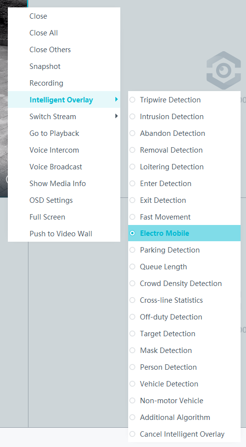
Parking Detection
Feature Description
Definition
Parking detection is used to detect whether a vehicle parks in a detection area for a time longer than the preset threshold. If so, an alarm is generated.
- Allows users to specify multiple detection areas (polygons).
- Displays alarm information including the alarm type, occurrence time, duration, and object labeling.
Customer Benefits
Intelligent analysis can be used to automatically detect vehicles that have been parked in a detection area for a long time, reducing labor costs and improving efficiency. Applicable intelligent analysis functions vary depending on application scenarios.
Application Scenario
Parking detection can be used to perform situation awareness on the parking duration of vehicles entering a parking area.
Requirements
NE |
Version Requirement |
License Requirement |
Function |
|---|---|---|---|
HWT-IVS1800 |
10.0.0 and later versions |
N/A |
Clears parking detection alarms. |
iClient S100 |
V2.0.0 and later versions |
N/A |
Allows users to configure behavior analysis and alarm display in the camera web system. |
SDC |
10.0.0 and later versions |
N/A |
Supports behavior analysis (perimeter detection). Enhanced perimeter detection is recommended. |
Feature Configuration (Based on Cameras)
Scenario Description
Table 4-202 describes the support for this feature in different client scenarios.
Prerequisites
- You have enabled behavior analysis for the camera and set global parameters on the iClient S100. For details, see Setting Global Parameters (Configuring Frontend Behavior Analysis on the iClient S100).
Procedure (on the LDU)
To view the configuration guide video, you can click in the upper left corner on the Configuration tab page, and scan the QR code.
- Log in to the LDU as the admin user. ( Logging In to the LDU)
- Click
 in the upper left corner.
 - Choose .
- Configure parking detection, as shown in Figure 4-219.
The following table describes the parameters.
Table 4-203 Parameter descriptionType
Parameter
Description
Detection Area
Detection switch
Button for enabling or disabling parking detection.
No.
ID of a detection area. A maximum of four detection areas can be drawn.
Operation
Column containing the icons for drawing or deleting a detection area on the live video image.
To draw a detection area, select polygon vertices on the video image and right-click the image. The system automatically connects the selected vertices to form a closed area.
Switch
Button for enabling or disabling a detection area.
Configuration
Alarm Sensitivity
Detection sensitivity of the system.
The value ranges from 1 to 100. A larger value indicates higher sensitivity.
Alarm Interval (s)
Interval at which alarms are checked, in seconds.
Stop Duration Threshold (s)
Parking duration threshold, in seconds. When the parking duration exceeds the threshold, an alarm is triggered.
The value ranges from 10 to 900.
Sound And Light Alarm
NOTE:The configurations of this function cannot be applied to other devices.
Audio switch/Twinkle switch
Indicates whether to produce audible alarms (playing audio files) or visual alarms (blinking light) when an alarm is triggered.
Audio Output
Audio file to be played when an alarm is triggered.
- You can directly use this function when an intelligent IR/white-light camera with intercom is used.
- To use this function when a camera other than the intelligent IR/white-light camera with intercom is used, you need to set audio parameters for the camera and connect the camera to an external audio output device.
Frequency
Number of times for playing an audio file when an alarm is triggered.
Twinkle Freq
Frequency at which the light blinks when an alarm is triggered. You can set this parameter to Low frequency, Medium frequency, or High frequency as required.
Currently, the visual alarm (blinking light) function is available only for intelligent IR/white-light cameras with intercom. You need to set light-related parameters.
Twinkle Time(s)
Period in which the light blinks when an alarm is triggered.
- Configure an alert plan, as shown in Figure 4-220.
Table 4-204 describes the key parameters.
Table 4-204 Parameter/Button descriptionParameter/Button
Description
Add
Button for adding an alert plan. A maximum of eight alert plans are supported.
Delete All
Button for deleting all alert plans.
Button for enabling or disabling an alert plan. If you toggle on Status, the alert plan takes effect.
Day
Date on which an alert plan is executed.
The default value is Every Day.
Mode
Mode in which an alert plan is executed.
- Weekly
- One-off
- Configure an alarm linkage policy, as shown in Figure 4-221.
Table 4-205 describes the key parameters.
Table 4-205 Parameter descriptionType
Parameter
Description
Common Linkage
Display ID
Indicates whether to display the status icon of the camera that triggers an alarm on the live video viewing page. This function is used to notify users of an alarm generated by the current camera.
Full-Screen Alarm
Indicates whether to display alarms in full screen mode.
After this function is enabled, if a camera triggers an alarm and the live video viewing page is displayed on the LDU, the live video of the camera is played in full screen mode for 5s.
CAUTION:If another alarm is generated when live video is being played in full screen mode, this function is not triggered.
Send Email
- Indicates whether to send email notifications. After this function is enabled, the system sends an email to the configured email recipient when a service alarm is generated.
- You can click to customize the alarm email recipient and email body.
The email address for sending service alarms needs to be customized on the OMU portal.
For details about how to set the email address for sending service alarms, see How Do I Configure Connection to the SMTP Server?.
Recording
Channel
Camera to be linked to record video when an alarm is triggered.
Duration(s)
Customized recording duration. The value ranges from 5 to 3600, in seconds. You are advised to set this parameter to a value greater than or equal to 60 (default).
Triggered Snapshot
Channel
Camera to be linked to take snapshots when an alarm is triggered.
NOTE:If both snapshot taking and email sending are configured for alarm linkage, you can obtain both the alarm-triggered snapshots and the snapshots sent in the email.
Stop Recording
Channel
Camera to be linked to stop video recording when an alarm is triggered.
I/O Alarm
Channel ID
Alarm reporting channel.
Duration(s)
Customized alarm linkage duration.
The value ranges from 1 to 3600, in seconds.
NOTE:If the specified alarm linkage duration is different from the I/O alarm output duration configured in How Do I Connect Cables and Configure Alarm Input and Output Ports?, the shorter alarm duration is used.
For example, if the I/O alarm output duration is set to 20s and the alarm linkage duration is set to 30s, the actual alarm output duration is 20s.
Invoke Preset Position
Channel
Camera to be linked. When a service alarm is generated, the linked camera rotates to the specified preset position.
Before enabling preset position linkage, ensure that a preset position has been configured for the camera to be linked. For details about how to configure a preset position, see Feature Configuration.
Device
Name of the camera that is linked to a preset position.
Position
Preset position linked to the camera.

Procedure (on the iClient S100)
- Configure the algorithm mode.
- On the iClient S100 home page, choose Maintenance Management > Smart Configuration.
- Select a camera connected to a main device and choose .
- Set Algorithm to Behavior analysis.
After the algorithm mode is switched, the camera will restart for the setting to take effect. To configure intelligent services, wait for about 3 minutes after the restart.
- Click Save.
- Configure parking detection.
- On the iClient S100 home page, choose Maintenance Management > Smart Configuration.
Select a camera connected to a main device and choose .
- Set related parameters, as shown in Figure 4-222. Table 4-206, Table 4-207, and Table 4-208 describe the parameters and buttons.
Table 4-206 Parameter/Button description
Parameter/Button
Description
Alarm Detection Interval(s)
Interval at which the system checks for new alarms, in seconds. If any alarm is detected, the system reports the alarm to the iClient S100.
Parking time(s)
Vehicle parking duration threshold, in seconds. An alarm is generated when the vehicle parking duration exceeds the specified value.
The value ranges from 10 to 900.
Sensitivity
Detection sensitivity.
The value ranges from 1 to 100. A larger value indicates higher sensitivity.
Enable audio alarms/Enable light flashing alarm
Indicates whether to produce audible alarms (playing audio files) or visual alarms (blinking light) when an alarm is triggered.
Audio Output: Audio file to be played when an alarm is triggered.
Times: Number of times for playing an audio file when an alarm is triggered.
Area
Button for adding a detection area. A maximum of four detection areas are supported.
Delete
Button for deleting a selected detection area.
Table 4-207 Audible and visual alarm parametersParameter
Description
Requirement on the Camera
Enable audio alarms
Indicates whether to produce audible alarms (play audio files) when an alarm is triggered.
- You can directly use this function when an intelligent IR/white-light camera with intercom is used.
- To use this function when a camera other than the intelligent IR/white-light camera with intercom is used, you need to set audio parameters for the camera and connect the camera to an external audio output device.
Audio file
Audio file to be played when an alarm is triggered.
To import an audio file to the iClient S100, choose Maintenance Management > Video Device > Device List on the home page, double-click the required camera that is connected to a device, and add an audio file on the Audio Channel tab page.
Playback times
Number of times for playing an audio file when an alarm is triggered.
Enable light flashing alarm
Indicates whether to produce visual alarms (blinking lights) when an alarm is triggered.
Currently, these functions are available when an intelligent IR/white-light camera with intercom is used. You need to set light-related parameters.
White light illuminator
Frequency at which the light blinks when an alarm is triggered. You can set this parameter to Low, Middle, High, or Steady on as required.
Flash duration (s)
Period in which the light blinks when an alarm is triggered.
- Click Save.

Feature Verification
Viewing Alarms (on the LDU)
- Log in to the LDU as the admin user. ( Logging In to the LDU)
- View alarms.
- Viewing real-time alarms
- Right-click on the desktop and choose Live > Alarm List.
- Click and select the type of alarms to be viewed, as shown in Figure 4-223.
- Click an alarm card in the alarm list to view the alarm in full screen mode, as shown in Figure 4-224.
- By default, the alarm-triggered video is 10s long (5s before and 5s after the alarm time).
- If you click , the alarm list on the left stops refreshing the latest alarms. If you click again, the system refreshes all new alarms generated after the alarm refresh stops.
- Viewing historical alarms
- Right-click on the desktop and choose Retrieval.
- Choose Event Retrieval.
- View alarms, as shown in Figure 4-225.
You can click the Browsing Status icon to switch the alarm browsing mode. Alarms in the alarm center can be browsed in card or list mode.
- Viewing real-time alarms
Viewing Alarms (on the iClient S100)
- Viewing real-time intelligent analysis results
- On the iClient S100 home page, choose .
- Double-click an online camera in the Devices area or drag the online camera to a live video pane. Then you can view live video from this camera.
- Right-click a live video pane and choose Intelligent Overlay > Parking Detection, as shown in Figure 4-226. The real-time intelligent analysis result is superimposed on the video image.
- Viewing alarms
For details about how to view the latest or historical alarms, see Viewing Alarms (on the iClient S100).
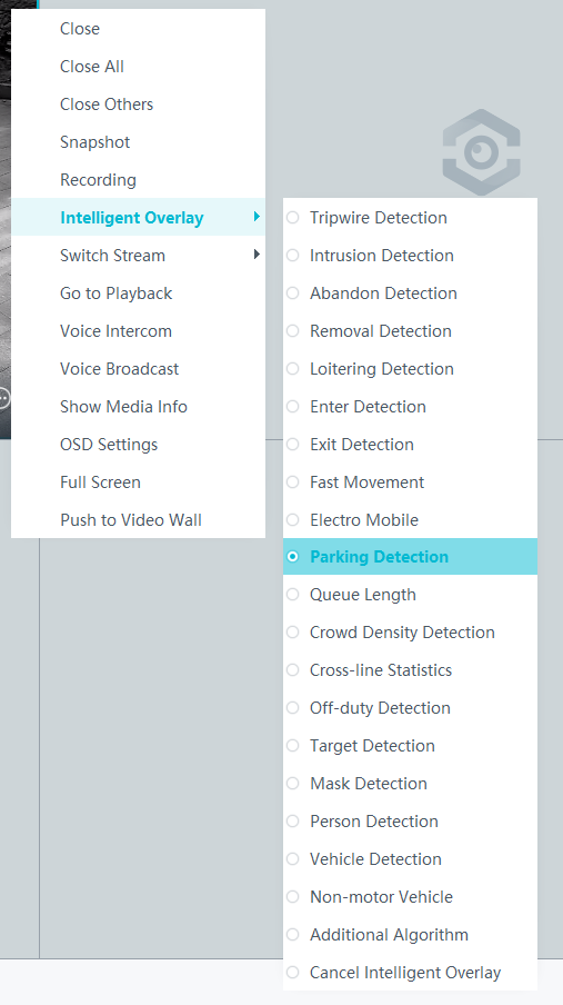
- Public Configurations
- Context
- Setting Global Parameters (Configuring Frontend Behavior Analysis on the LDU)
- Setting Global Parameters (Configuring Backend Behavior Analysis on the LDU)
- Setting Global Parameters (Configuring Backend Behavior Analysis on the iClient S100)
- Setting Global Parameters (Configuring Frontend Behavior Analysis on the iClient S100)
- Intrusion Detection
- Loitering Detection
- Abandoned Object Detection
- Removed Object Detection
- Tripwire Crossing Detection
- Area Entry Detection
- Area Exit Detection
- Fast Movement Detection
- Electric Bike Detection
- Parking Detection